20 Brocade MLX Series and NetIron XMR Hardware Installation Guide
53-1003821-01
Router modules
1
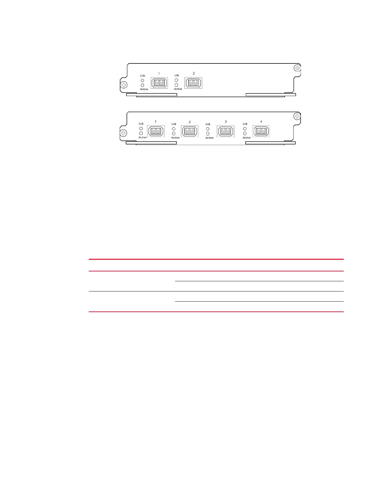
The front panel of the 2-port module includes the following features:
• Two LEDs per port (as described in Table 7)
• Two 10 Gbps Ethernet XFP optics ports
The front panel of the 4-port module includes the following features:
• Two LEDs per port (as described in Table 7)
• Four 10 Gbps Ethernet XFP optics ports
10 Gbps Ethernet interface module LEDs
Gen-1 2-port and 4-port interface modules have LEDs that indicate the status of each port, as
described in Table 7.
10 Gbps Ethernet ports
The Gen-1 2-port or 4-port Ethernet modules (BR-MLX-10Gx4-X) have either two or four physical
ports that allow you to connect your router to other network routers at a speed of 10 Gbps.
You must insert XFP-compliant fiber-optic transceivers in each port you intend to use.
XFP-compliant transceivers provide an optical or physical medium-dependent (PMD) interface for
single- or multi-mode fiber that can be used with either the LAN physical layer (PHY) or WAN
physical layer (WAN PHY).
For a list of XFP-compliant fiber-optic transceivers supported for Gen-1 2-port or 4-port modules,
refer to the latest version of the Brocade Optics Family Data Sheet, available online in the following
location:
http://www.brocade.com/downloads/documents/data_sheets/product_data_sheets/optics-famil
y-ds.pdf
For more information about fiber-optic transceivers and associated cabling, refer to “Installing a
fiber-optic transceiver” on page 218.
TABLE 7 Gen-1 2-port or 4-port 10 Gbps Ethernet module LEDs
LED Location State Meaning
Link Left of each
Ethernet port
On A link is established with the remote port.
Off A link is not established with the remote port.
Active Left of each
Ethernet port
On The port is transmitting and receiving packets.
Off The port is not transmitting or receiving packets.
 Loading...
