Brocade MLX Series and Brocade NetIron XMR Hardware Installation Guide 129
53-1002373-02
Installing a Brocade MLXe-32 router
2
2. Route cables from slots #3 and #4 up through comb A. Refer to Figure 92.
3. Route cables from slots #5 and #6 up through comb B.
4. Route cables from slots #7 and #8 up through comb C.
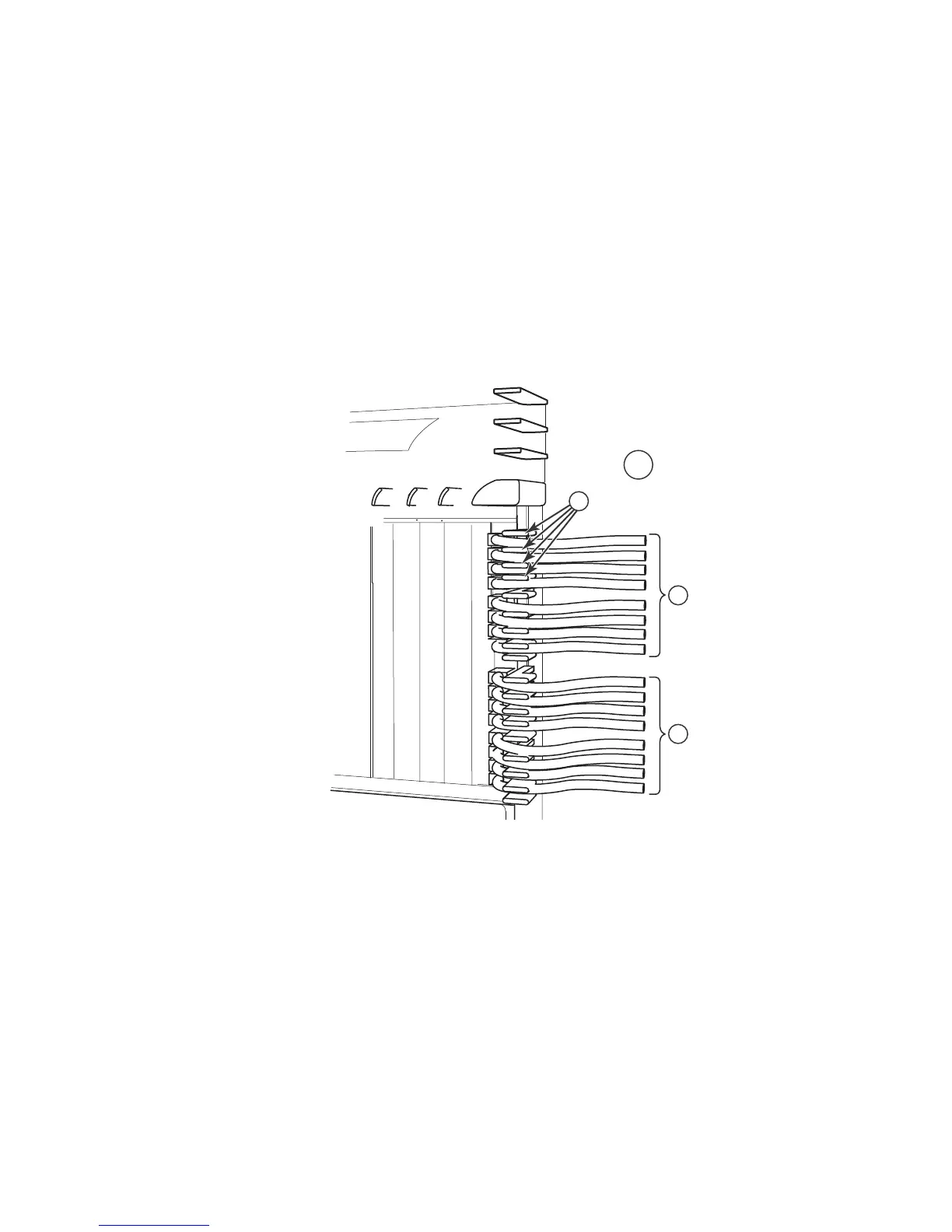
Cable routing for the upper-right quadrant
Route cables from slots in numerical order starting with the cables for slot #15.
1. Route cables from slots #15 and #16 directly to the right through the side comb. Refer to
Figure 93.
FIGURE 93 Routing Upper-right quadrant cables to the right
1 Upper right quadrant 3 Cables from slot #15
2 Side combs (18) 4 Cables from slot #16
 Loading...
