Brocade MLX Series and Brocade NetIron XMR Hardware Installation Guide 377
53-1002373-02
Replacing fan assemblies
8
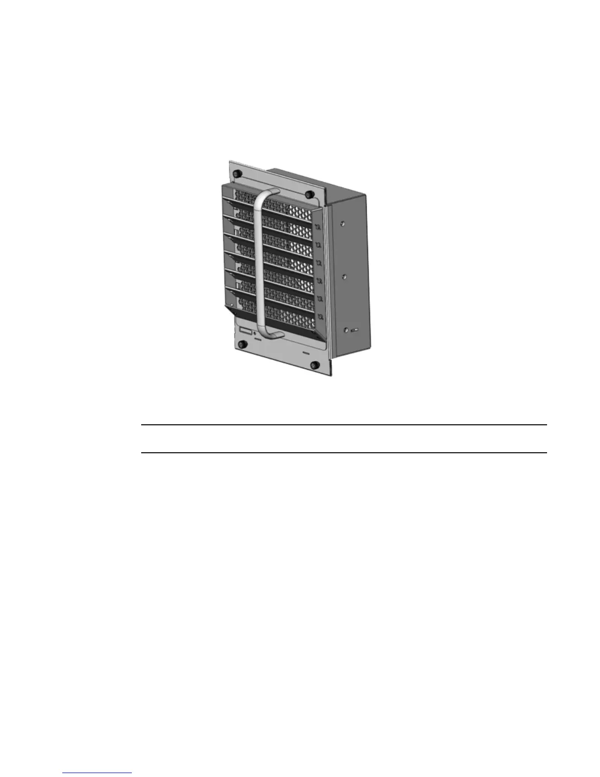
6. Place the handle over the upward deflector aligning the handle with the screw holes and
secure the handle to the upward deflector and fan assembly faceplate with the two screws.
Refer to Figure 251.
FIGURE 251 Upward deflector oriented correctly between the handle and fan assembly faceplate
7. Re-attach the fan assembly faceplate to the fan assembly by securing three screws on each
side.
Replacing the tape is not required.
Reinstalling the modified fan assembly in the chassis
To reinstall the modified fan assembly, complete the following steps:
1. Insert the modified fan assembly into the fan slot and push the assembly in until the fan
assembly faceplate is flush with the chassis. Pushing the fan assembly in seats the fan
connector in the router connector.
2. Secure the fan assembly to the router by replacing and tightening the four screws.
3. Check the fan status LED in the lower left corner of the faceplate. It will glow red momentarily
when power is applied, and then it will change to green when the fan comes up to speed.
4. To verify that the fan is operating correctly, access the CLI and enter the show chassis
command.
 Loading...
