Once you have completed the preliminary installation preparations (refer to Preliminary EIA rack mount installation steps on page 138),
complete the following steps to install your router in a 2-post EIA rack.
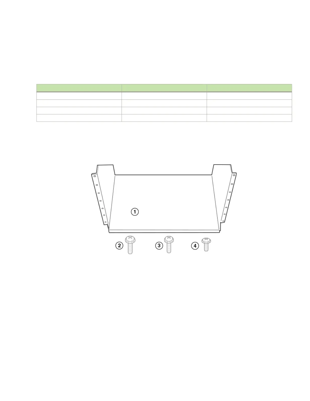
1. Unpack the Open Frame EIA 310-D Rack Mount Kit. The following table provides you with a list of the kit components, and the
following gure shows you the contents.
TABLE 32 Open Frame EIA 310-D Rack Mount Kit contents
Part Number Description Quantity
42-1000452-01 Saddle 1
52-0000211-01 10-32 x 5/8 inch screws 14
52-1000141-01 12-24 x 1/2 inch screws 14
52-1000138-01 M6 x 12 mm screws 14
NOTE
Use the screws specied for the type of rack. Make sure you have the items listed in the previous table, and shown in
the following gure.
FIGURE 61 Open Frame EIA 310-D Rack Mount Kit contents
1. Saddle
2. 10-32 x 5/8 inch screws
3. 12-24 x 1/2 inch screws
4. M6 x 12 mm screws
2. Allow 35U in the rack to accommodate the router. Refer to the following gure for system alignment.
• The saddle requires 1U of permanent space in the rack.
• The router requires 33U of space in the rack, plus 1U temporary space above for installation.
Installing a Brocade MLXe Series-32 router
Brocade NetIron MLXe Series Hardware Installation Guide
53-1004203-04 139

 Loading...