Operation Manual
FT1020G3 Rev 2.4
14
4 x programmable non-supervised inputs (I0-I3), see drawing no. F732-02.
6 x 24 V DC outputs (power supply outputs for Web-server II (1598), routing
equipment and external equipment), see drawing no. F732-01.
2 x non-programmable relay outputs for routing equipment (Fire alarm output
for Fire brigade tx and Fault output for Fault tx), see drawing no. F732-02.
Space & connectors for two TLON connection boards (5090), see drawing
no. F732-03.
RS485 and 24 V DC outputs for Display Units (1728, 1736, 1826), see
drawing no. F732-03.
Connector for expansion boards (4580, 4581 & 4583), see drawing no. F765.
Connectors for Web-server (1598), see drawing no. F765.
Connectors for power supply and batteries, see drawing no. F732-01
• Power supply, see drawing no. F765
Switch mode power supply, 230 V
AC / 24 VDC.
Space and connection cables for two Sealed Lead-Acid backup batteries (12
V, up to 40 Ah). Battery box available for larger batteries
Battery temperature sensor.
• Space for up to six expansion boards 458x.
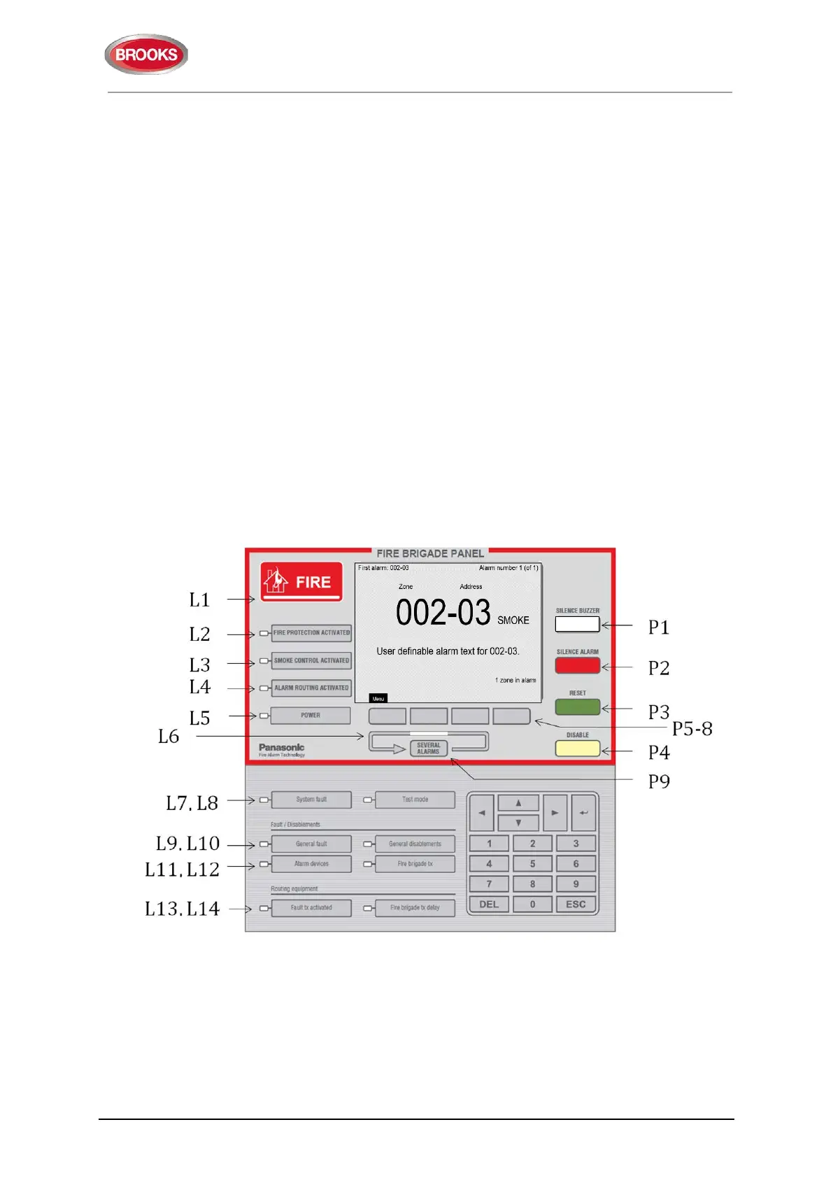
3.4 Front Display
Figure 3 FT1020G3 front display
The fire brigade or fire services personnel use the integrated FBP inside red boarder to
see which alarm point / zone(s) have activated a fire alarm and take the required
operational control of the system. Fire brigade personnel can control active alarms via the
buttons and keys P1-P9 within the FBP. In the graphical display, the information displayed
in the upper part is dependent on how many alarm points / zones have generated fire
alarm. In the middle part, the fire alarms will be shown, i.e. one alarm point or one zone
together with a user definable alarm text (if programmed) plus some other information.


 To Next Page