Operation Manual
FT1020G3 Rev 2.4
28
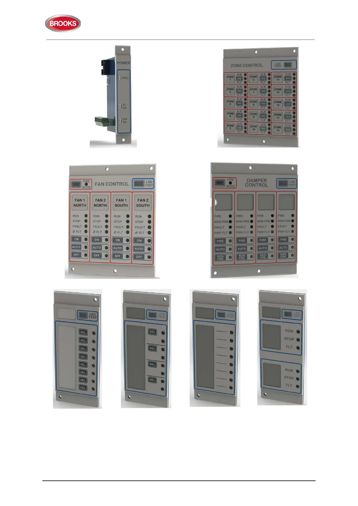
Figure 11: 1204 Power Monitor Module
Figure 12: 1205 Zone Control Module
Figure 13: 1206 Fan Control Module
Figure 14: 1211 Damper Control Module
Figure 15: 1207– 8
Key/ 8 LED Control &
Display Module
Figure 16: 1208 - 4
Key/ 8 LED Control
and Display Module
Figure 17: 1209 – 8
LED Display Module
Figure 18: 1210 – 6
LED Pump Status
Module
Each display module is manufactured of 3 parts: PCB, plastic spacer and decal label. The
following is a brief description for each display module:
• 1204 – Power Monitor module, designed as an interconnection point between a
rack of new display modules and the FT1020G3. One module per ancillary rack
 Loading...