Operation Manual
FT1020G3 Rev 2.4
20
4 Control Unit Options
4.1 I/O Matrix 4582
25
The I/O matrix board is an interface between the FDCIE (COM loop) and various types of
application boards e.g. AS1668 fan control board, Zone Disable and indication board, LED
mimic board, etc.
Up to 24 of the I/O matrix boards 4582 can be used in FT1020G3 if no Expansion Boards
type 4580, 4581 or 4583 are used. The limitation of the I/O matrix configuration as follows:
• Up to six I/O matrix boards can be programmed in FT1020G3 FDCIE as type
“Zone control” and / or “Generic” e.g. NZ fire brigade panel, LED mimic, etc.
• Up to 24 I/O matrix boards can be programmed as type “Fan control” if no other
I/O matrix are used for generic or zone control i.e. up to 96 fans can be controlled
and displayed in FT1020G3.
• A combination of any of the two previous options can be used if the maximum
number of each application is maintained.
In the generic applications, each I/O matrix board can operate up to 48 LEDs (outputs) and
16 switches (inputs). All outputs and inputs can be configured individually via EBLWin.
The I/O matrix board can be used remotely, it requires 24V
DC and COM loop in addition to
an application board.
Note: Jumper links JP1-JP3 are used to set the I/O matrix board number (0-3) and
JP5-JP6 are used to set the application type (generic, fan control or zone control). For
more details refer to the Technical / Programming Manual and/or Technical Datasheet
TDS040
4.2 AS1668 Fan Control Module
The fan control module is designed to meet the requirements of the Australian standard
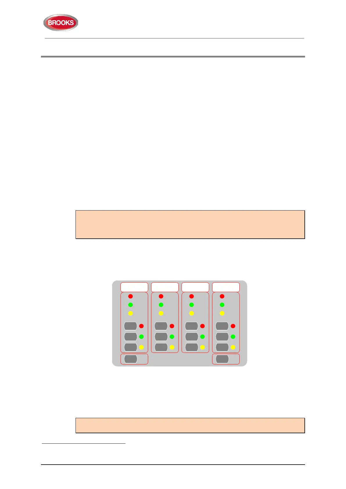
AS1668.2. The front display is shown in Figure 4 below.
Figure 4 AS1668 Fire fan control Display
Each fan control module consists of an I/O matrix 4582 and display / control board
(SUB902). Each module can control and indicate the status of up to 4 different fans. Up to
24 x AS1668 fan control modules can be used to provide 96 fan interfaces if no other
Expansion Boards 458X or 4582 are used.
Note: The total number of fan modules must be reduced by one for every other option
fitted, e.g. zone module, generic module, Expansion Board, etc.
25
In the new 19” rack format, the I/O matrix circuit is incorporated into the AS1668 fan control and display board as well as zone
control board, new subassemblies are SUB1024 and SUB1023 respectively.
FF F F
AA A A
NN N N
On
On On
AutoAuto Auto Auto
OffOff Off Off
Fault
Running
Fault
Running
Stopped
Fault
Stopped
Fault
Running
Stopped Stopped
Running
Fan
Reset
LED
Test
On
1668 FAN CONTROL
 Loading...