Technical Data and Installation
SMART KTF 2000 - 2.1 -
2
2 2
2 –
––
–
TECHNICAL DATA AND INSTALLATION
TECHNICAL DATA AND INSTALLATIONTECHNICAL DATA AND INSTALLATION
TECHNICAL DATA AND INSTALLATION
Technical Features
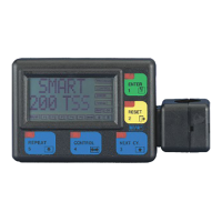
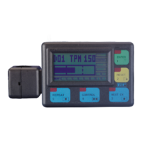
SMART KTF 2000 Terminal
Power supply voltage
24 Vdc ± 20%
Maximum absorption
100 mA
Dimensions
135 x 95 x 40 mm
Operating Temperature range
10° - 60 °C
LCD graphic display
80 x 40 mm
Integrated Touch-pad
5 membrane buttons with integrated red LED
Protection 2 fuses 5 x 20 – 1A
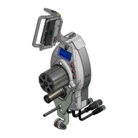
Installation
The installation of SMART KTF 2000 terminal simply consists in connecting the
terminal itself to the KTF/.. devices using a communication cable through which the
data exchange between terminal and devices will occur.
The following page show some connection examples of SMART KTF 2000 terminal
for application using KTF/100HP yarn feeding devices and KTF/RW systems
respectively.
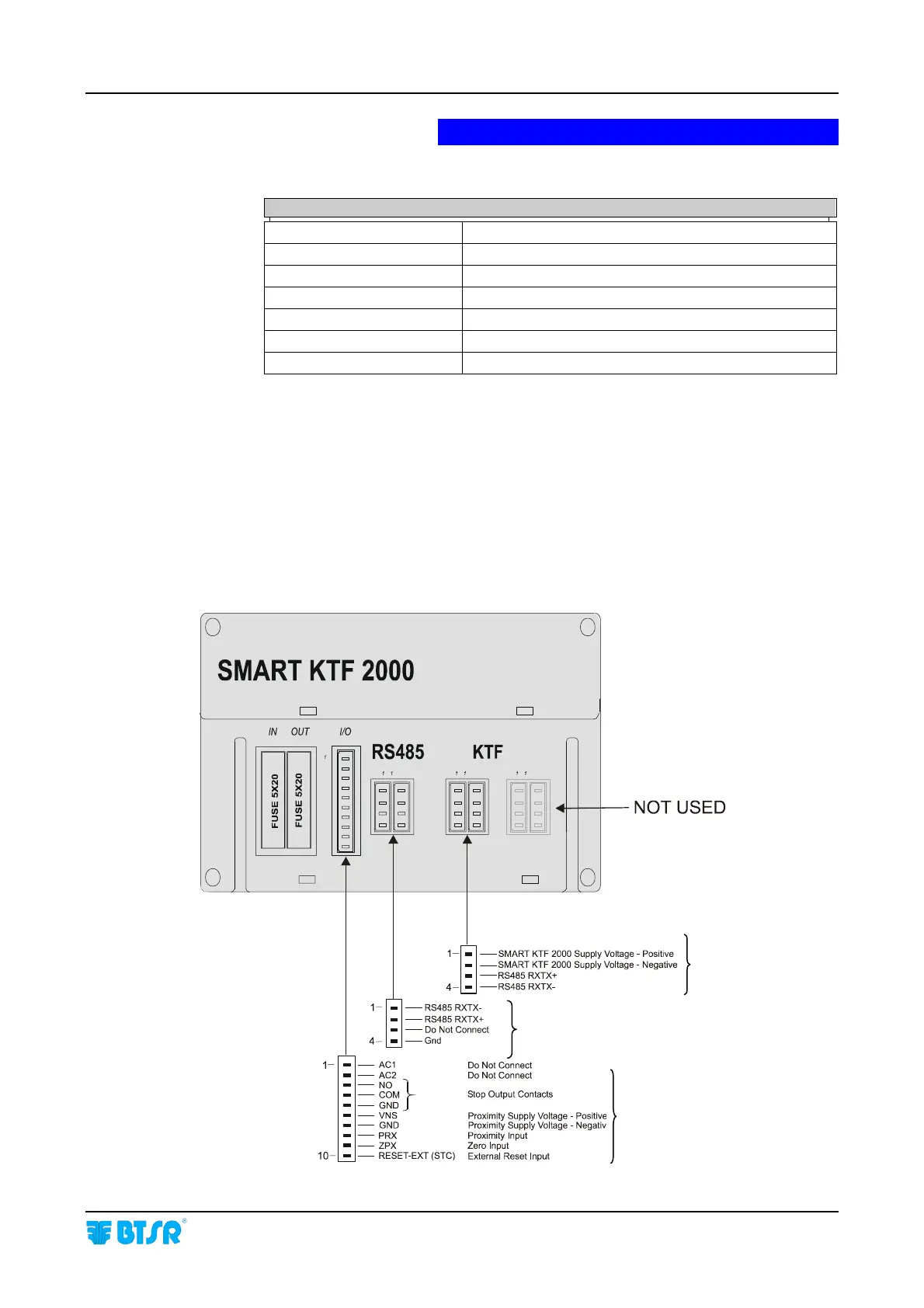
Interface Connectors on SMART KTF 2000
KTF/.. Connection
Used for LINK function
Machine Interface