50
Electrical installation and Wiring
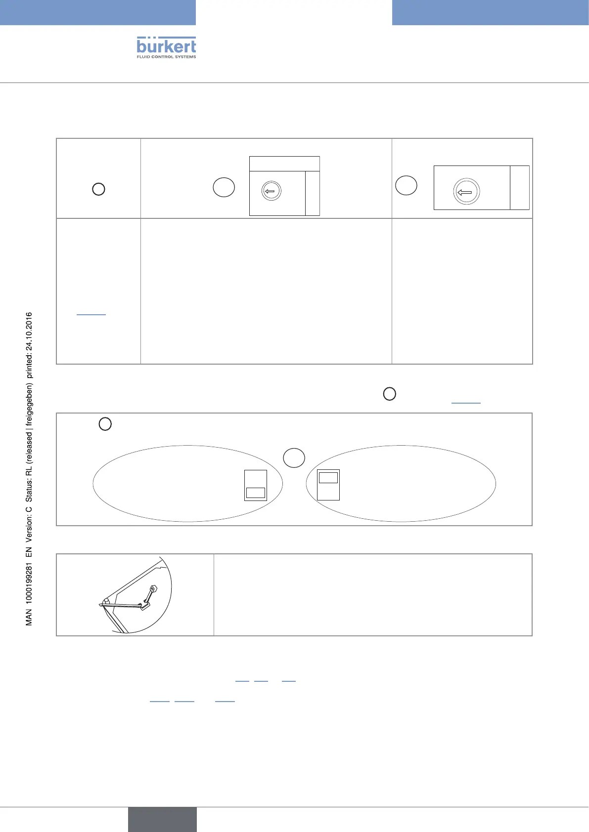
Tab. 2 : Position of selectors "SENSOR TYPE", "SENSOR SUPPLY" and "LOAD" on the 8025 Batch in compact
version, the 8035 Batch or the SE35 Batch
Selector
"SENSOR TYPE"
C
Selector "SENSOR SUPPLY"
SUPPLY
+5V
L+
(L+)-12V
A
Selector "LOAD"
B
LOAD
39K
2.2K
→ Set the
selector on
"NPN/PNP"
(Fig. 26)
The flow sensor of the device needs a minimum voltage
supply of 5 V DC :
→ If the device is fed with a voltage ≥ 12 V DC and
< 17 V DC, set the voltage selector "SENSOR
SUPPLY" on "5V" or "L+".
→ If the device is fed with a voltage ≥ 17 V DC, the
voltage selector "SENSOR SUPPLY" can be set to any
position.
→ If the device is fed with a 115/230V AC voltage, set
the voltage selector "SENSOR SUPPLY" on "L+".
→ Set selector "LOAD":
• either on "2.2k": the load
resistance R is then 2,2 kW
• either on "470": the load
resistance R is then 470 W
→ If the device is energized with a 115/230 V AC power supply, set selector
D
as shown in Fig. 27.
Selector
D
makes it possible to configure the supply voltage of the device in a 115/230 V AC version.
→ Energize the device
with a 230 V AC voltage.
→ Energize the device
with a 115 V AC voltage.
D
230V
115V
Fig. 27 : Selector of the supply voltage on a 115/230 V AC version
→ Before wiring the device insert the supplied cable clips into the slots of
the electronic board.
Fig. 28 : Inserting the cable clips
→ Install the device as described in chap. 7.2, 7.3 or 7.4.
→ Wire acc. to chap. 8.11, 8.14 and 10.6.
→ Secure the power supply cable and the relay connection cables, with the cable clips.
→ Close the housing and tighten the 4 screws of the cover.
English
Type 8025 - 8035 - SE35 BATCH