2.7. Location Monitor
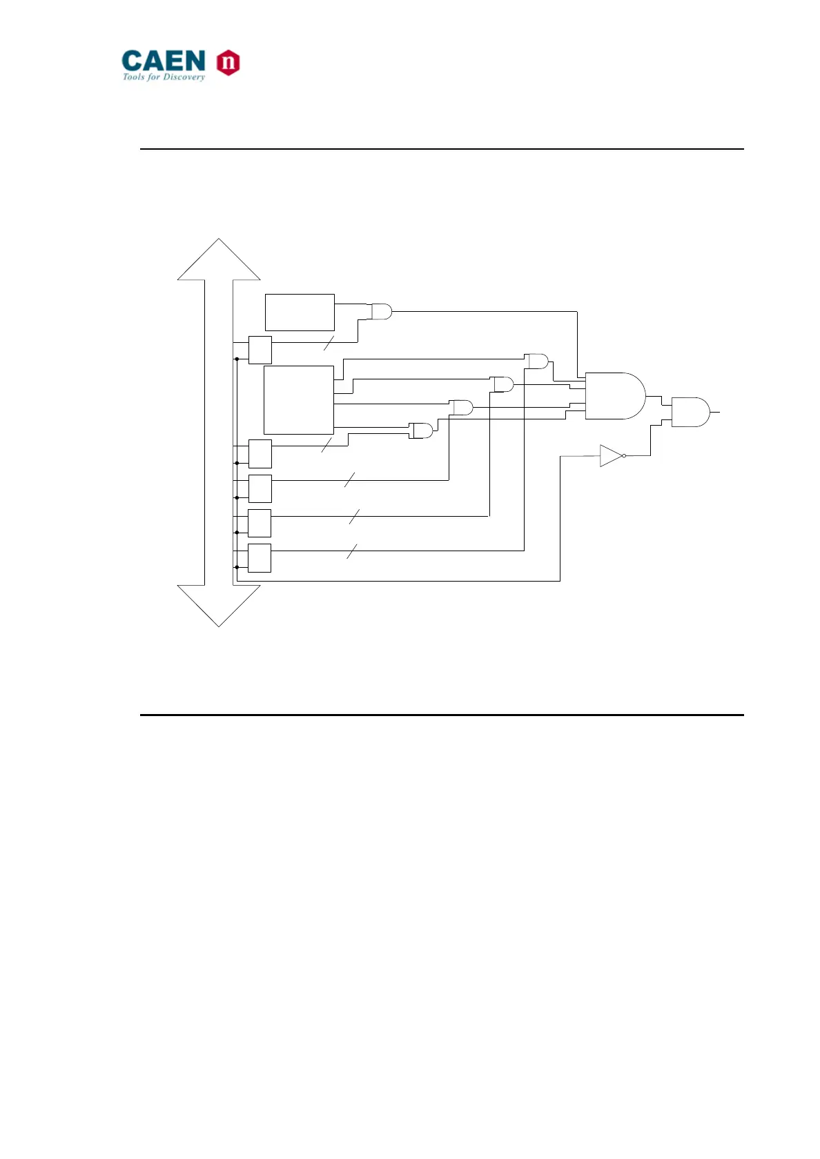
The V2718 monitors the cycles on the bus, whether they are held by itself or by other
masters, and produces a Trigger Out LMON signal as soon as a particular cycle is
performed (see Fig. 5). The LMON out is available by default as front panel signal.
Fig. 5: The Location Monitor
2.8. VME bus First Slot Detector
The First Slot Detector module samples BG3IN* immediately after reset to determine
whether the V2718 resides in slot 1. The VME bus specification requires that BG[3:0]*
lines be driven high during reset. This means that if a board is preceded by another
board in the VME bus system, it will always sample BG3IN* high after reset. BG3IN* can
only be sampled low after reset by the first board in the crate (there is no preceding
board to drive BG3IN* high). If BG3IN* is sampled at logic low immediately after reset
(due to the master internal pull-down), then the V2718 is in slot 1 and becomes SYSTEM
CONTROLLER: otherwise, the SYSTEM CONTROLLER module is disabled. This
mechanism may be overridden via dip switch setting: the SYSTEM CONTROLLER bit is
“forced” to one by setting to ON PROG_0, and is “forced” to zero by setting to ON
PROG_1; note that such switches must always be in “opposite” positions (see § 3.5.1).