EasyManua.ls Logo

Caen V2718 - Internal Jumpers; Fig. 38: Component Location

Default Icon
79 pages
Print Icon
To Next Page IconTo Next Page
To Previous Page IconTo Previous Page
Loading...
Document type:
Title:
Revision date:
Revision:
User's Manual (MUT)
Mod. V2718 VME PCI Optical Link Bridge
03/07/2018
11
NPO:
Filename:
Number of pages:
Page:
00106/03:V2718.MUTx/11
V2718_REV11.DOC
79
40
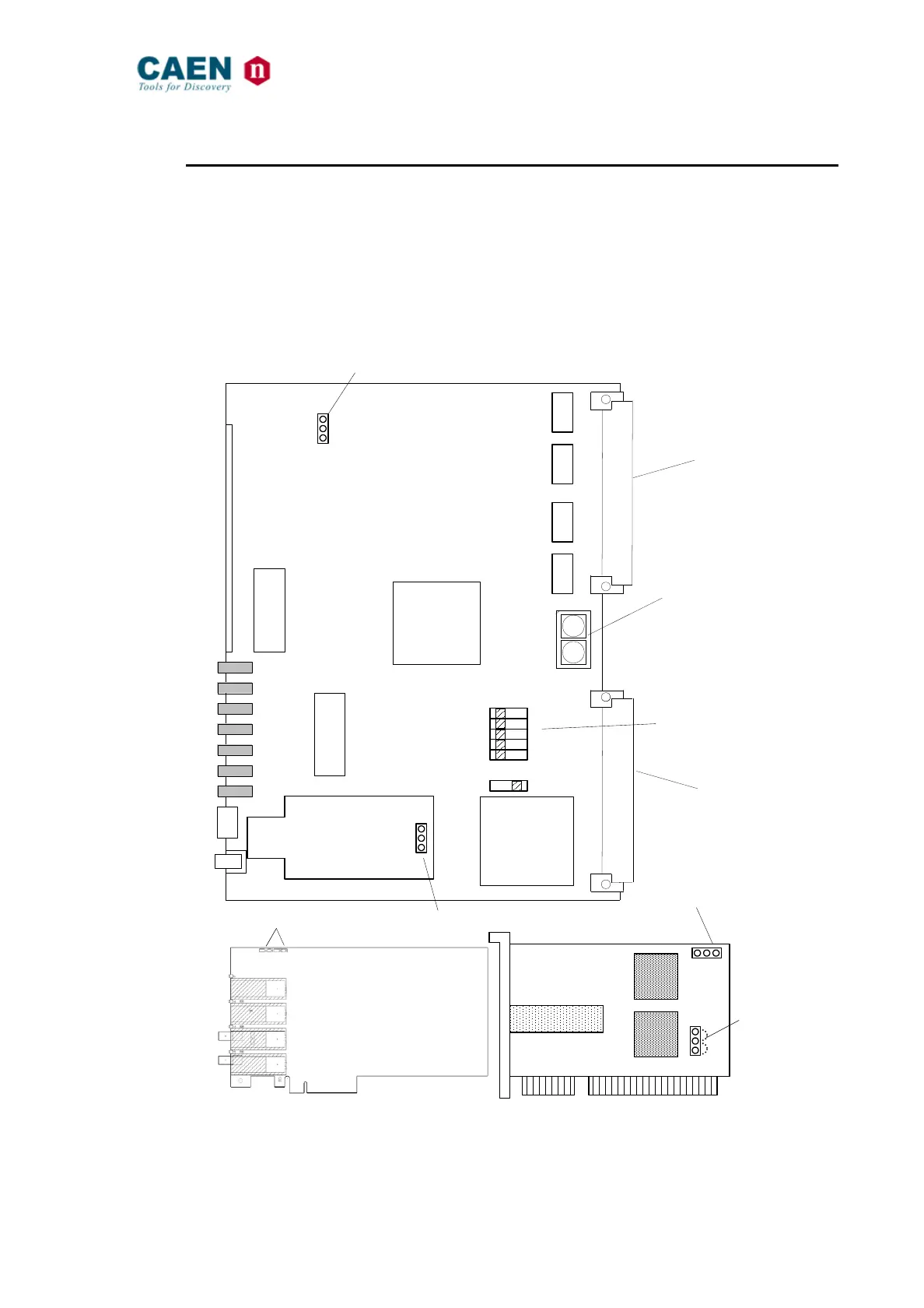
3.5.2. Internal jumpers
Three jumpers (one on the V2718, one on the A2719 piggy back board and one on the
A2818 PCI board) allow to select whether the “Standard” or the “Back up” firmware must
be loaded at power on; jumpers’ position is shown in Fig. 38. The A2818 is supplied by
the PCI bus; one jumper on the A2818 allows to select the power supply (+3.3V or +5V);
if you are using a +5V PCI bus, then jumper position must be 1-2, if you are using a
+3.3V PCI bus, then jumper position must be 2-3; please refer to the used PCI bus
specification in order to select the proper power supply.
Fig. 38: Component Location
for Base address selection
Rotary
switches
VME P1
connector
VME P2
connector
PROG
I/O
OFF ON
0
1
2
3
4
TTLNIM
DIP switches
SW8
SW9
BA[7..4
]
BA[3..0
]
STD
BKP
STD
BKP
STD
BKP
Firmware
sel.
Firmware
sel.
Firmware
sel.
A2818
A2719
V2718
1
2
3
1-2=5V
2-3=3.3V
Power
supply
sel.
A3818
S1 S2
Firmware
sel.

Table of Contents