2.13.13. Output Multiplexer Set register
(Base Address + 0x0C, D16, read/write)
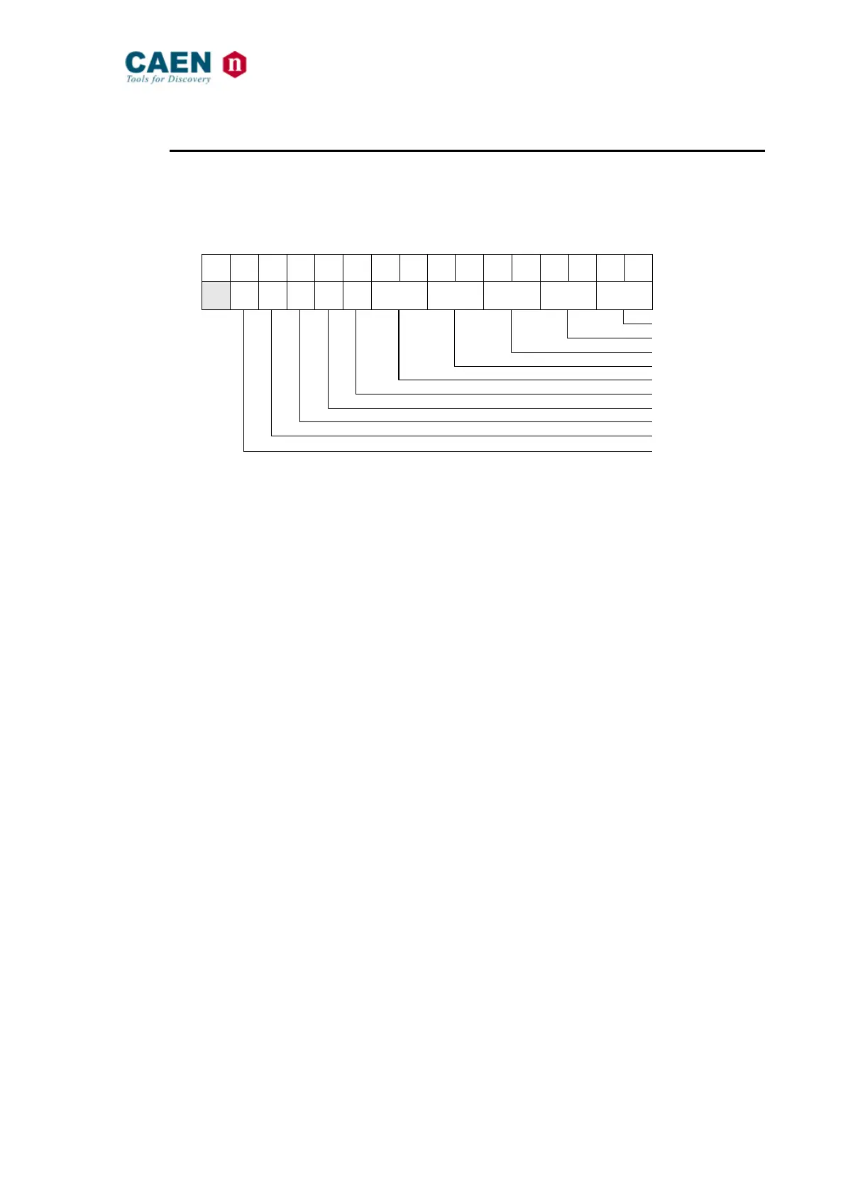
This register allows to set the OUT[4..0] polarity as well as the source of such signals:
1 = set; 0 = leave previous setting.
Fig. 16: Output Multiplexer Set register
OUTPUT_0 SOURCE: 00 = Data Strobe
01 = Input 0 AND Input 1
10 = Pulser A Output
11 = Output Register
OUTPUT_1 SOURCE: 00 = Address Strobe
01 = Input 0 AND Input 1
10 = Pulser A Output
11 = Output Register
OUTPUT_2 SOURCE: 00 = Data Acknowledge
01 = Input 0 AND Input 1
10 = Pulser B Output
11 = Output Register
OUTPUT_3 SOURCE: 00 = Bus Error
01 = Input 0 AND Input 1
10 = Pulser B Output
11 = Output Register
OUTPUT_4 SOURCE: 00 = Location Monitor
01 = Input 0 AND Input 1
10 = Scaler End Count
11 = Output Register
OUTPUT POLARITY: 0 = Direct
1 = Inverted