COPYRIGHT
©
2000 CANON INC. 2000 2000 2000 2000 CANON iR5000/iR6000 REV.0 JULY 2000
CHAPTER 3 STANDARDS AND ADJUSTMENTS
3-31 T
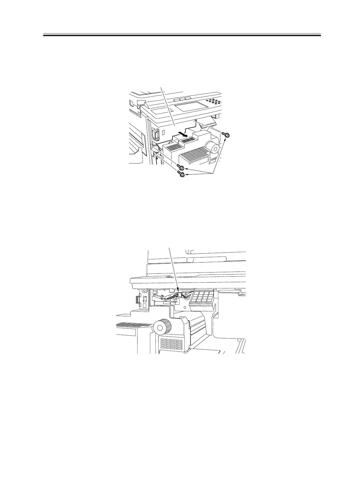
4) Open the front cover, and slide out the pickup feeding unit to the front.
5) Remove the three screws [3], and detach the front switch cover [4].
F03-803-02
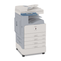
6) Free the cable of the potential control PCB from the cable clamp, and disconnect the
connector (4-pin) [5] connected to the DC controller PCB.
F03-803-03
7) Put the pickup feeding unit back into its initial position, and fit the door switch tool in
the door switch assembly; then, turn on the main power switch.
8) Make the following selections in service mode, and check to find out that the reading
during initial rotation is between 0 and 30: COPIER>DISPLAY>DPOT>DPOT-K.
If the reading is not between 0 and 30, suspect a fault on the DC controller PCB.
9) Turn off the main power switch, and remove the door switch tool.
10) Remove the jumper wire from the DC controller PCB.
[3]
[4]
[5]
Download Free Service Manual at http://printer1.blogspot.com