MV750i E, MV730i E, MV700i E, MV700 E, MV690 E
DISASSEMBLING
9
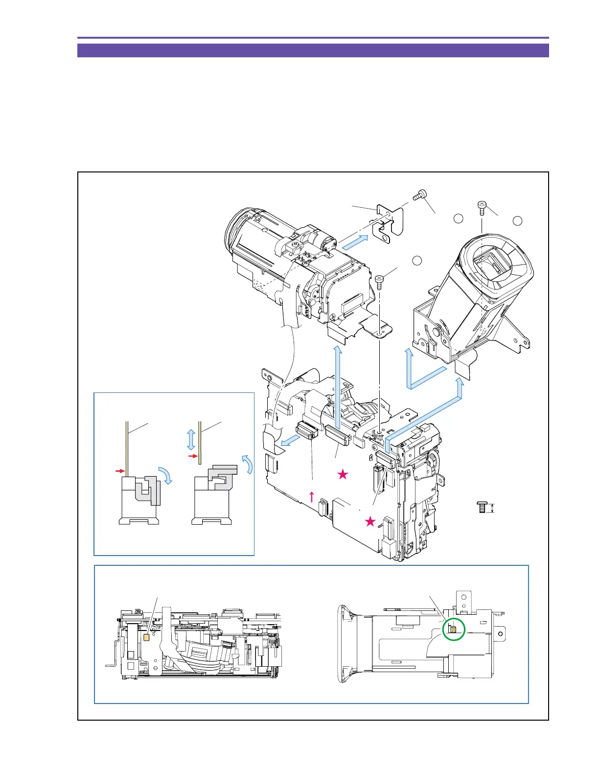
1-7 Separation of CVF Unit and Camera Unit
(1) Remove a screw (b × 1), disconnect the CN1501, and slide the CVF Unit sidewise (toward Right Cover) to detach.
(2) Remove two screws (b × 2), disconnect the CN1100 and CN1200, and detach the GND Plate and Camera Unit.
Note : (1) Use the new type connector (MAIN P.C.B., CN1200) as illustrated.
(2) Pay attention not to bend the GND Plate.
<Note on Reassembling>
(1) For mounting the CVF Unit, insert the claw A on its bottom into hole B on the Recorder Unit, and slide it sidewise (toward Left
Cover).
Fig. 6
3mm
Metal
M1.7
b
Note (1)
Note on Reassembling (1)
Recorder Unit top
CVF Unit Bottom
Lock
Unlock
(2)
(1)
(1)
(2)
(2)
GND Plate
CVF Unit
Camera Unit
(2) - b
(1) - b
(2) - b
Hole B
Claw A
CN1200
CN1100
CN1501
FPC
FPC
Metal
contact
Metal
contact