MV750i E, MV730i E, MV700i E, MV700 E, MV690 E
DISASSEMBLING
10
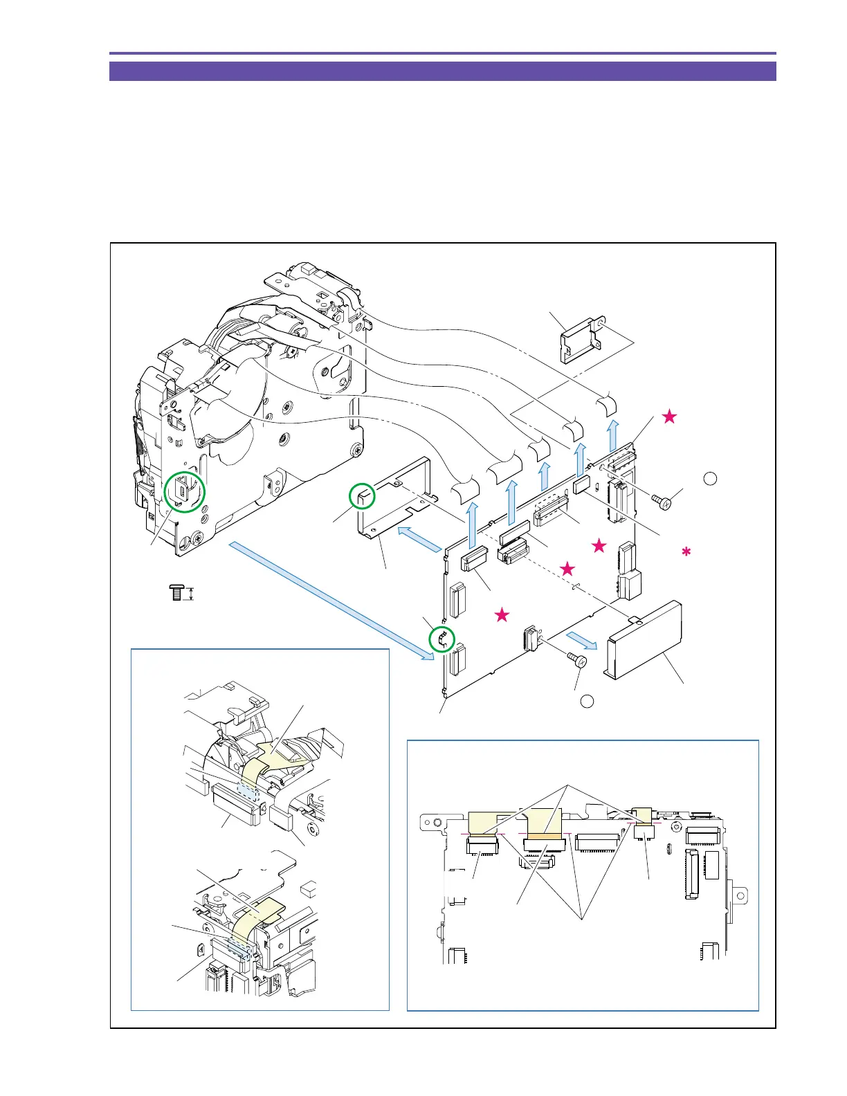
1-8 Separation of MAIN P.C.B.
(1) Remove two screws (b × 2), disconnect the CN300, CN301, CN302, CN303 and CN2000, and detach the MAIN P.C.B.
(2) Remove the HA Shield from the MAIN P.C.B., unsolder it, and detach the PM1 and 2 Shields.
<Note on Reassembling>
(1) Process the DRUM FPC and LOADING MOTOR FPC so as to bend permanently as illustrated.
(2) Insert flexible cables into CN302, CN303 and CN2000 according to the flexible cable insertion line on the MAIN P.C.B. as
illustrated.
(3) For mounting the MAIN P.C.B., engage the dowel A with part B of the Recorder Holder.
Fig. 7
3mm
Metal
M1.7
b
Note on Reassembling (1)
Note on Reassembling (2)
CN302
CN303
DRUM FPC
MAIN P.C.B.
Flexible cable bump
Align the flexible cable bump
with the insertion line.
Insertion line
CN2000
CN300
CN1100
CN2000
CN300
CN303
CN302
CN301
CN2000
(1) - b
(1) - b
PM2 Shield
PM1 Shield
HA Shield
MAIN P.C.B.
(2)
(1)
(2)
Solder
Dowel A
Part B
LOADING MOTOR FPC
CN1501
CN301