MV750i E, MV730i E, MV700i E, MV700 E, MV690 E
TECHNICAL DESCRIPTION
14
5. System Control, Servo
5-1 Outline of System Control, Servo
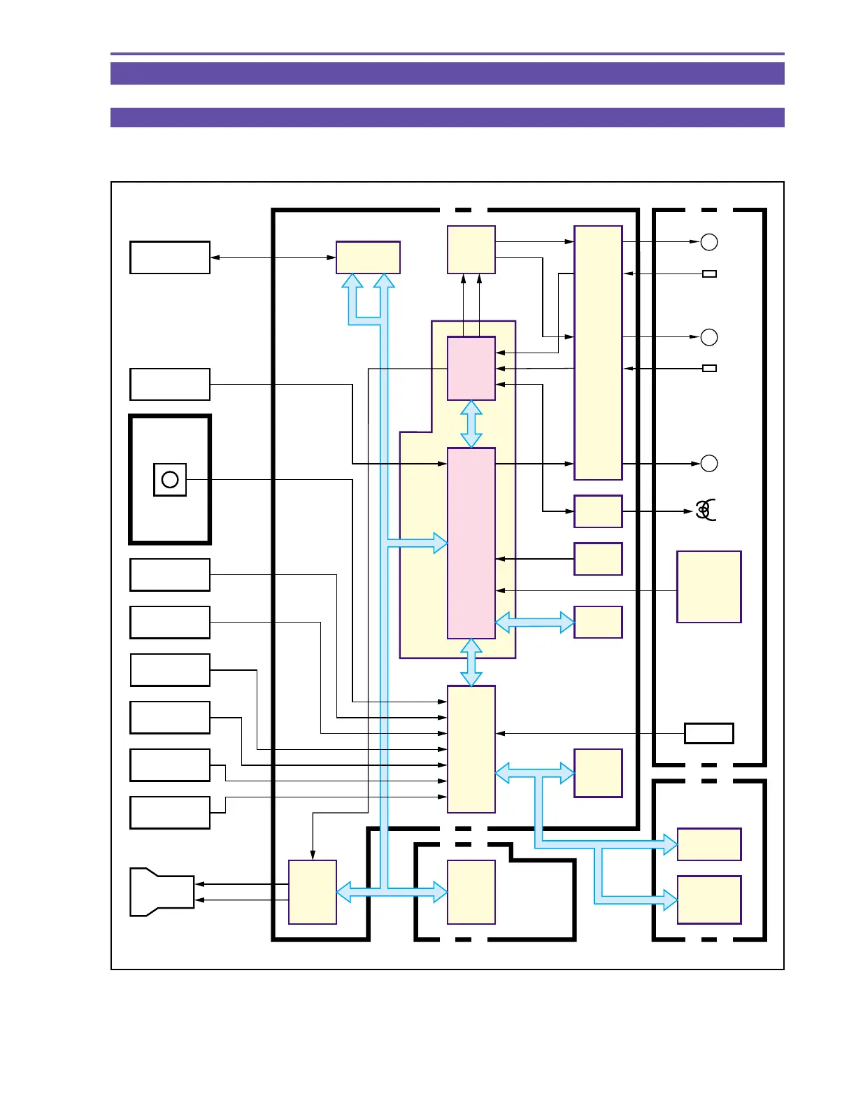
Figure 12 shows the overall configuration of the system control & servo circuit, plus the flow of data. System control is performed
by the FR MI-COM (IC2301) and MODE MI-COM (IC100) on MAIN P.C.B.
Fig. 12
DMC III
MAIN P.C.B.
LCD P.C.B.
JACK1
P.C.B.
CA
P.C.B.
HEAD
REMOTE
CONTROL
SIGNAL
RECEIVER
M
FG/PG
DRUM
CAPSTAN
LOADING
FG
M
M
IC901
EEPROM
ZOOM SW
START/STOP
SW
PHOTO SW
DIAL SW
R-KEY
EJECT SW
POWER SW
IC903
LCD
DRIVER
IC3201
DC/DC
CONVERTER
FR
MI-COM
IC1103
DIGIC DV
VIC
IC100
MODE
MI-COM
IC801
AIF4
IC1501
EVF
DRIVER
IC1200
LENS
DRIVER
IC2000
VRP2
IC2300
FLASH
MEMORY
CARD
IC1002
CDS
AGC
A/D TG
LENS
PWM D
PWM C
IC301
MOTOR
DRIVER
IC2301
VIC4
CAPSTAN
DRIVER
DRUM
DRIVER
MODE SW
C.DOWN SW
BOT/EOT
SENS.
DEW
REEL FG
MIC
LOADING
DRIVER
D-VS
C-VS
DFG/PG
CFG
IRIS DRIVE
MOTOR DRIVE