MV750i E, MV730i E, MV700i E, MV700 E, MV690 E
DISASSEMBLING
3
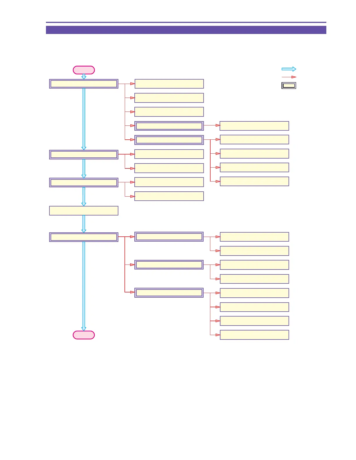
1-1 Disassembling / Reassembling Flowchart
(1) Find the replacement part on the chart, and disassemble it following the instruction on chart.
(2) Reassembling can be made by reversing the disassembling procedures.
START
: MAIN FLOW
: SUB FLOW
: MAIN UNIT
1-14 R Key P.C.B.
1-10 Jack P.C.B.
1-11 Mic Ass'y
1-3 R-LCD Unit
1-4 Front Cover Unit
1-22 LI P.C.B.
1-22 DC P.C.B.
1-6 Jack2 P.C.B.
1-5 Rear Cover Unit
1-6 Camera Recorder CVF Unit
1-15 LCD Unit
1-7 Recorder Unit
1-7 CVF Unit
1-7 Camera Unit
1-15 Right Cover Unit
1-15 DSW FPC Ass'y
1-15 Speaker
1-18 LCD Hinge Unit
1-19 Backlight Ass'y
1-19 LCD P.C.B.
1-16 RR Key FPC
1-19 LCD Ass'y
1-28 CA P.C.B.
1-29 CCD Ass'y
1-30 Lens Ass'y
1-29 CCD P.C.B.
1-8 Main P.C.B.
1-9 DMC lll
1-26 CVF Ass'y
1-26 CVF P.C.B.
END