MV750i E, MV730i E, MV700i E, MV700 E, MV690 E
DISASSEMBLING
12
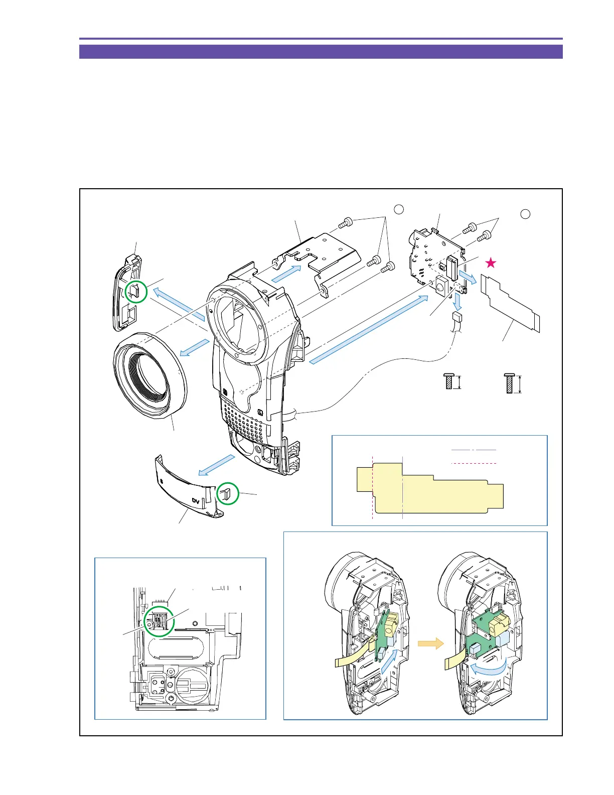
1-10 Disassembly of Front Cover Unit - 1
(1) Remove two screws (c × 2), disconnect the CN43, and detach the JACK P.C.B.
(2) Disconnect the CN51, and detach the JACK-MAIN FPC from the JACK P.C.B.
(3) Disengage the claws A and B, and detach the Jack Cover and F Jack Cover.
(4) Remove three screws (e × 3), and detach the Shoe Base and Lens Ring.
<Note on Reassembling>
(1) Before using a service part of JACK-MAIN FPC, process it so as to bend permanently as illustrated.
(2) For mounting the JACK P.C.B., insert the JACK side into the Front Cover, and mount it with the JACK-MAIN FPC kept bent.
(3) Mount the MIC Ass’y Cable on CN43, and then push it in part C.
Fig. 9
Metal
M1.7
(self tap)
4.5mm
e
c
6mm
Metal
M1.7
(self tap)
Note on Reassembling (1)
Note on Reassembling (2)
Note on Reassembling (3)
(4) - e
(1)
(4)
(4)
(3)
(3)
(1) - c
Outer fold
Inner fold
MIC Ass'y Cable
Part C
F JACK Cover
JACK-MAIN FPC
JACK-MAIN FPC
JACK Cover
Lens Ring
Shoe Base
Claw B
JACK P.C.B.
CN51
CN43
CN43
(1)
Claw A