MV750i E, MV730i E, MV700i E, MV700 E, MV690 E
DISASSEMBLING
13
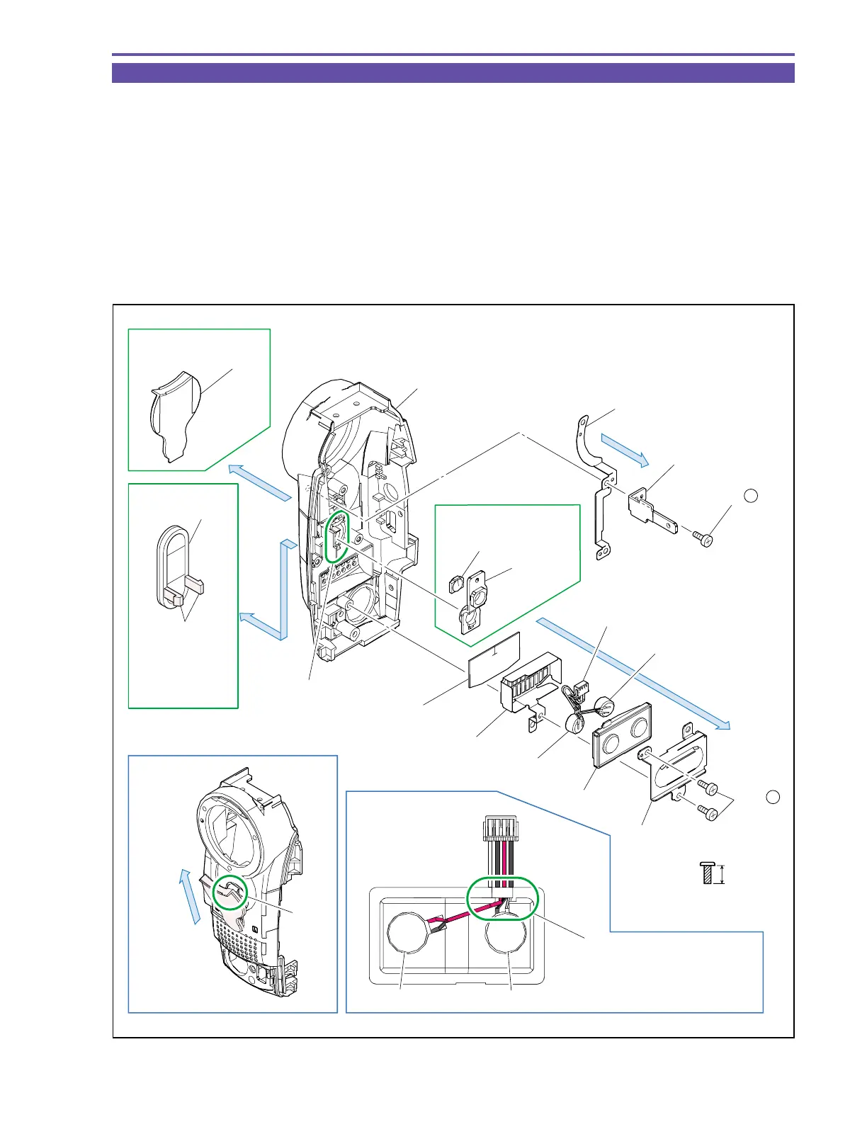
1-11 Disassembly of Front Cover Unit - 2
(1) Remove two screws (c × 2), and detach the MIC Plate, MIC Rubber, MIC Ass’y, MIC Shield and MIC Sheet.
(2) Remove a screw (c × 1), and detach the Joint Plate and Shoe GND Plate.
(3) Disengage the claw A, and detach the IR Window and LED Lens (MV750i E only).
Note : Pay utmost attention not to break the claw A.
(4) Detach the LED Window (MV750i E only).
Note : Using tweezers or the like, pull out and then remove upward the part B of the LED Window.
(5) Disengage the claw C, and detach the IR Window B (MV730i E, MV700i E, MV700 E, MV690 E only).
<Note on Reassembling>
(1) Do not stain nor scratch the LED Lens, IR Window and IR Window B when mounting them.
(2) Carry out wiring for the MIC Ass’y Cables as illustrated.
Fig. 10
Metal
M1.7
(self tap)
4.5mm
c
NOTE
Note on Reassembling (2)
Claw A
Claw C
White / Black
Red / Black
Front Cover
LED Lens
Shoe GND Plate
Joint Plate
MIC Sheet
MV750i E Only
MV730i E,
MV700i E,
MV700 E,
MV690 E Only
MIC Shield
MIC Ass'y
MIC Rubber
MIC Plate
IR Window
LED Window
IR Window B
(2)
(2) - c
(1) - c
(1)
(4)
(5)
Remove
upward
MV750i E Only
Part B
Arrange four Cables side
by side so as not to cross
Red / Black
White / Black