MV750i E, MV730i E, MV700i E, MV700 E, MV690 E
DISASSEMBLING
14
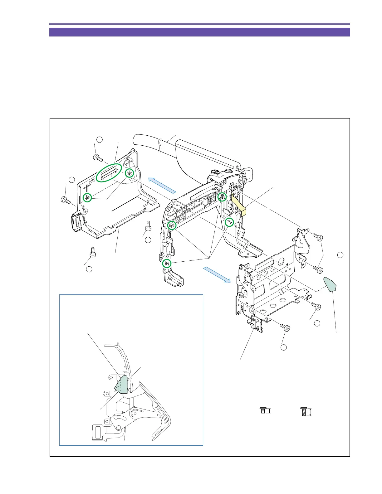
1-12 Disassembly of Left Cover Unit - 1
(1) Remove the Strap, and slightly open the Cassette Arm.
(2) Remove four screws (f × 4), and slide the claw A downward for detaching the Cassette Cover.
(3) Remove four screws (n × 4), and detach the Cassette Arm Ass’y and Cassette Arm Sheet.
<Note on Reassembling>
(1) Attach the Cassette Arm Sheet on an illustrated position.
(2) At a slightly (5º to 10º) open status, position the Cassette Arm Ass’y on dowel C of the Left Cover, and tighten the screws, paying
attention not to pinch the flexible cable of the Operation Key Ass’y.
(3) Engage the claw A and dowel B of the Cassette Cover with the Cassette Arm at an open status, and tighten the screws.
Fig. 11
f
2.5mm
Metal
M1.7
Note on Reassembling (1)
n
4mm
Black
M1.7
(self tap)
Cassette Arm Ass'y
Cassette Arm
Sheet
Attach according to contour with Cassette Arm open.
Attaching error ±0.5 mm from contour.
Sheet must not touch
stopper section.
(2) - f
(2) - f
(2) - f
(2) - f
Strap
Dowel B
Dowel C
Cassette Cover
(2)
Cassette Arm
Sheet
(3)
Claw A
(3) - n
(3) - n
(3) - n
Flexible cable of the
Operation Key Ass'y