MV750i E, MV730i E, MV700i E, MV700 E, MV690 E
DISASSEMBLING
15
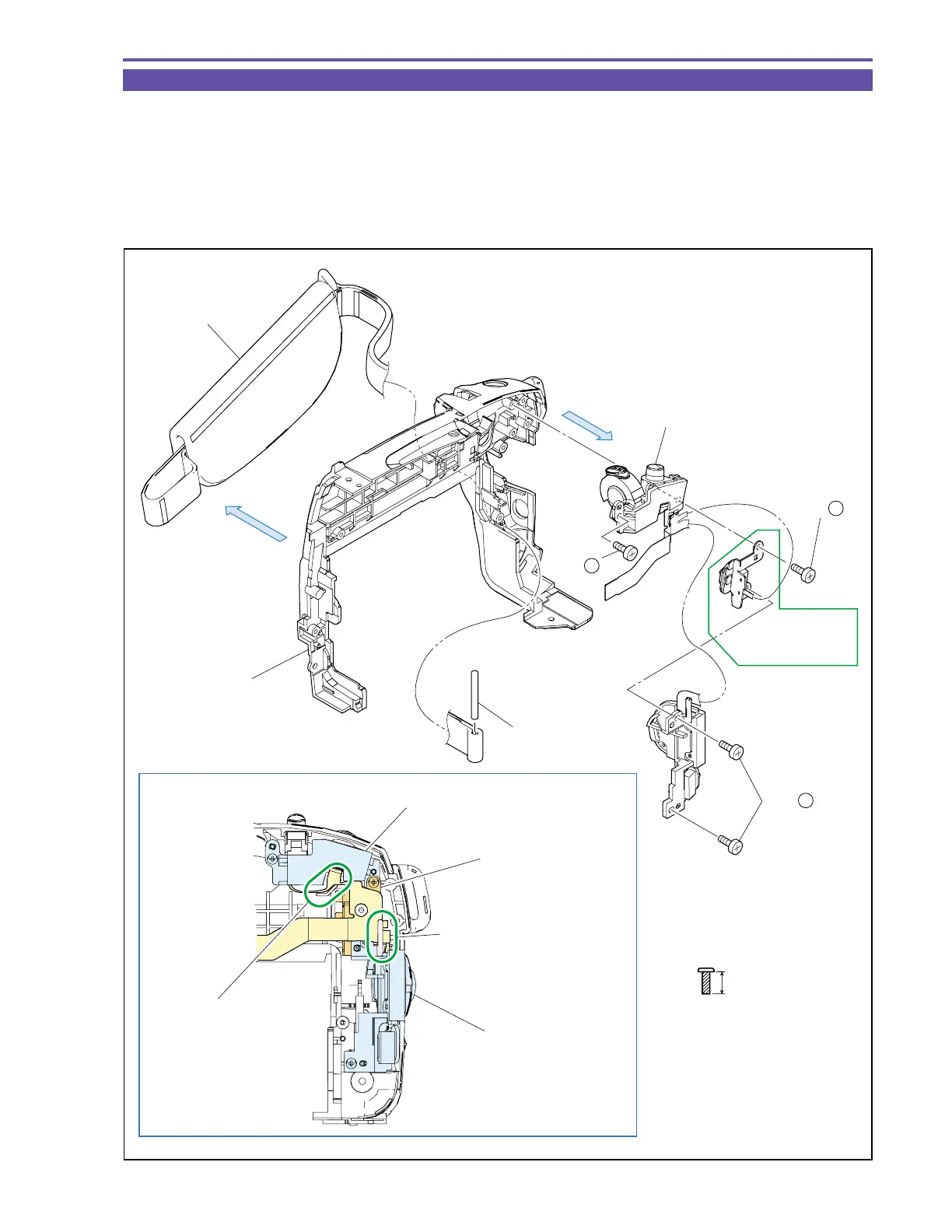
1-13 Disassembly of Left Cover Unit - 2
(1) Remove four screws (h × 4), and detach the Operation Key Ass’y.
(2) Remove the Shaft, and detach the Hand Strap.
<Note on Reassembling>
(1) For mounting the Operation Key Ass'y, pass the Shaft into the Hand Strap, and then attach the Zoom Key, Card/Tape Key (MV750i E,
MV730i E only) and Power Key in this order.
Also carry out handling for the FPC as illustrated and pay attention not to break them.
Fig. 12
h
5mm
Metal
M1.7
(self tap)
Note on Reassembling (1)
(1) - h
(1) - h
(1) - h
Hand Strap
(2)
(1)
Operation Key Ass'y
MV750i E,
MV730i E only
Shaft
Left Cover
Zoom Key
Card/Tape Key
(MV750i E,
MV730i E Only)
Power Key
Pass the flexible cable
inside the rib of Left Cover.
Pass the flexible cable
through the Power Key
hooking part.
Pay attention to relative position of
flexible cable and Key vertically.