MV750i E, MV730i E, MV700i E, MV700 E, MV690 E
SERVICE MODE · ADJUSTMENT
2
2. Setting
(1) Adjustments other than DMC-III : Perform adjustments in the product state.
(2) Tracking adjustment (DMC-III) and Envelope check : Perform them with the Setting A.
(3) Adjustments related to DMC-III other than Tracking adjustment, tape path system check and tape path system cleaning : Perform
them with the Setting B.
2-1 Setting A
Envelope Check)
(1) Peel the jig connecting sheet.
(2) Connect the extension connector (DY9-1387-000) to
CN2900.
(3) Observe the PB-RF waveform output from the extension con-
nector
Tracking Adjustment)
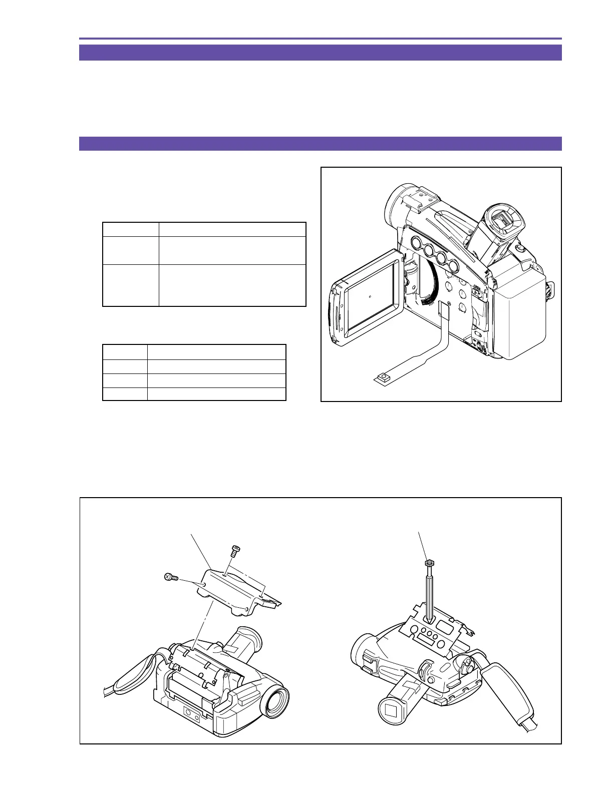
(1) Remove the CASSETTE COVER referring to Fig. 2 (a).
(2) When the posts are going to be adjusted, eject and remove the cassette once and perform the prospective adjustment as shown in
Fig. 2 (b).
(3) Repeat the observation of the PB-RF waveform and the prospective adjustment until fluctuation of envelope is re-moved.
Note :
When the tracking adjustment is going to be performed, refer to “5-8 Tape Path Adjustment” on p.25.
Fig. 1
Extension connector
MV750i E
DY9-1390-000
MV730i E
MV700i E
DY9-1394-000
MV700 E
(with remote control beam sensor)
MV690 E
Pin No. Signal Designation
3GND
15 SWP
19 PBRF
Fig. 2
(a) (b)
× 2
× 2
CASSETTE COVER
ADJUSTMENT DRIVER