MV750i E, MV730i E, MV700i E, MV700 E, MV690 E
DISASSEMBLING
18
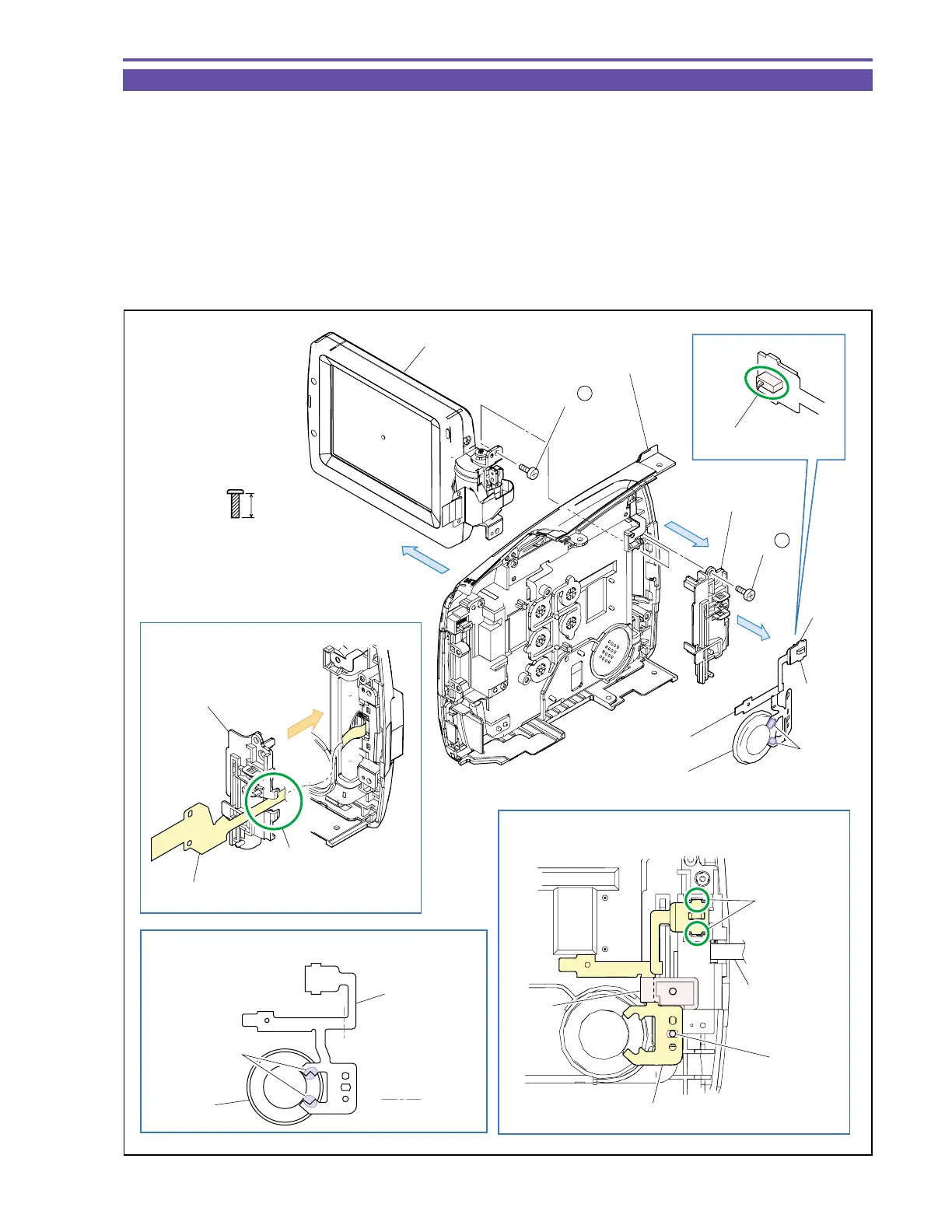
1-15 Disassembly of R-LCD Unit - 2
(1) Disengage the claw A, and detach the D SW FPC Ass’y and Speaker.
Note : Take care not to damage the switch lever of the D SW FPC Ass’y.
(2) Unsolder two points (α), and detach the Speaker from the D SW FPC Ass’y.
(3) Remove two screw (i × 2), and detach the RH Cover and LCD Unit.
<Note on Reassembling>
(1) For mounting the RH Cover, pass the LCD FPC Ass’y to the part A.
(2) Before using a service part of D SW FPC Ass’y, process it so as to bend permanently at the illustrated position.
(3) With the LCD Unit open as illustrated, engage the claw A of the D SW FPC Ass’y, pass it under the part B, and mount it on the
dowel C.
Fig. 15
i
5.5mm
Metal
M1.7
(self tap)
Claw A
Inner fold
Solder point
Claw A
Dowel C
Part B
Claw A
Note on Reassembling (1)
Note on Reassembling (2)
Note on Reassembling (3)
D SW FPC Ass'y
Speaker
LCD FPC Ass'y
D SW FPC Ass'y
(3)
LCD Unit
Right Cover Unit
RH Cover
(1)
(2) - α
D SW FPC Ass'y
Speaker
(3) - i
(3) - i
(3)
Part A
RH Cover
LCD FPC Ass'y
Note
The lever part of SW.