MV750i E, MV730i E, MV700i E, MV700 E, MV690 E
DISASSEMBLING
27
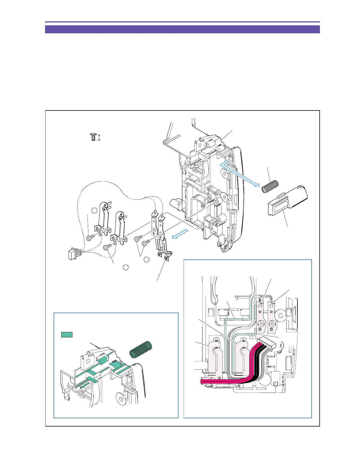
1-23 Disassembly of Rear Cover Unit - 2
(1) Remove four screws (l × 4), and detach the Batt Terminal Ass’y.
(2) Detach the Batt Eject Lever and Spring.
Note : Do not lose the Spring.
<Note on Reassembling>
(1) Mount the Batt Terminal Ass’y as illustrated.
<Instruction for Supply>
Sliding part of rail of Batt Eject Lever : Hanarl FL-778 (DY9-3026-010)
Spring : Hanarl FL-778 (DY9-3026-010)
Fig. 24
l
3.5mm
Metal
M1.7
(self tap)
Hanarl FL-778
Black
Red
Groove
(1)
(2)
(1) - l
(1) - l
(1) - l
Spring
Batt Terminal Ass'y
Batt Eject Lever
Rear Cover
Note on Reassembling (1)
Groove
Pass the white and gray wires through
groove of Rear Cover.
Instruction for Supply
White
Gray