3–3 62-11640
3.3 STARTING UNIT
WARNING
!
Under no circumstances should ether or any other starting aids be used to start the engine.
1. Place the START/RUN-OFF switch in the START/RUN position.
NOTE
The unit will automatically start in the operating state it was in (Engine Operation or Electric Operation)
when stopped.
2. The system will display the Carrier Transicold logo, display the default screen, present language selection
and the hour meter readings (if configured to do so) along with a test flash of the alarm light and light bar
amber LED’s. The system will then perform a start sequence, energize the buzzer, and then start the unit
automatically.
NOTE
If the unit attempts to start in Electric Operation, and power is not available, the A00073 − “NO
POWER − CHECK POWER CORD” alarm will be activated. This alarm will clear if power is restored.
If the alarm condition exists for five minutes and the Functions and Configurations are set to allow a
switch, the unit will switch to Engine Operation.
3. If there is an alarm present, the alarm message will be displayed in the MessageCenter and the alarm LED
will flash for 5 seconds. If one or more shutdown alarms are present, the alarm(s) must be cleared before
the unit will start.
4. If the unit is to be switched from Engine Operation to Electric Operation or from Electric Operation to Engine
Operation, refer to SWITCHING OPERATING STATE on the next page. Once the unit is operating in the
desired state, observe the MessageCenter. If the word “ACTIVE” or “MODIFIED” is displayed at the right,
the unit is equipped with IntelliSet settings, refer to Section 3.5.
5. If the LCD Display does not illuminate, check:
• Battery voltage. A booster battery may be needed.
• Check for blown fuse(s).
• Verify the harness connector at the back of the display module and all other module connectors are
securely attached.
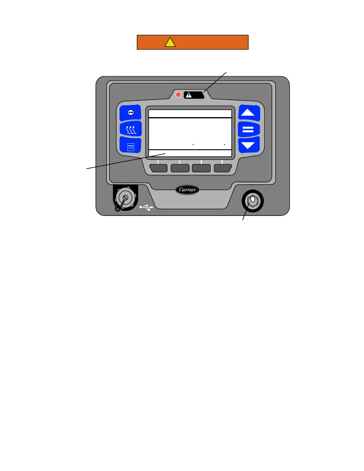
OFF
START/RUN
O
I
CONTINUOUS
START/STOP
MENU
ALARM
DEFROST
COOLDIESELSTART/STOP
STATUS OK
36
36
.2
BOX TEMPERATURE F SETPOINT F
4
3
1

 Loading...

