003237t
Figure 1
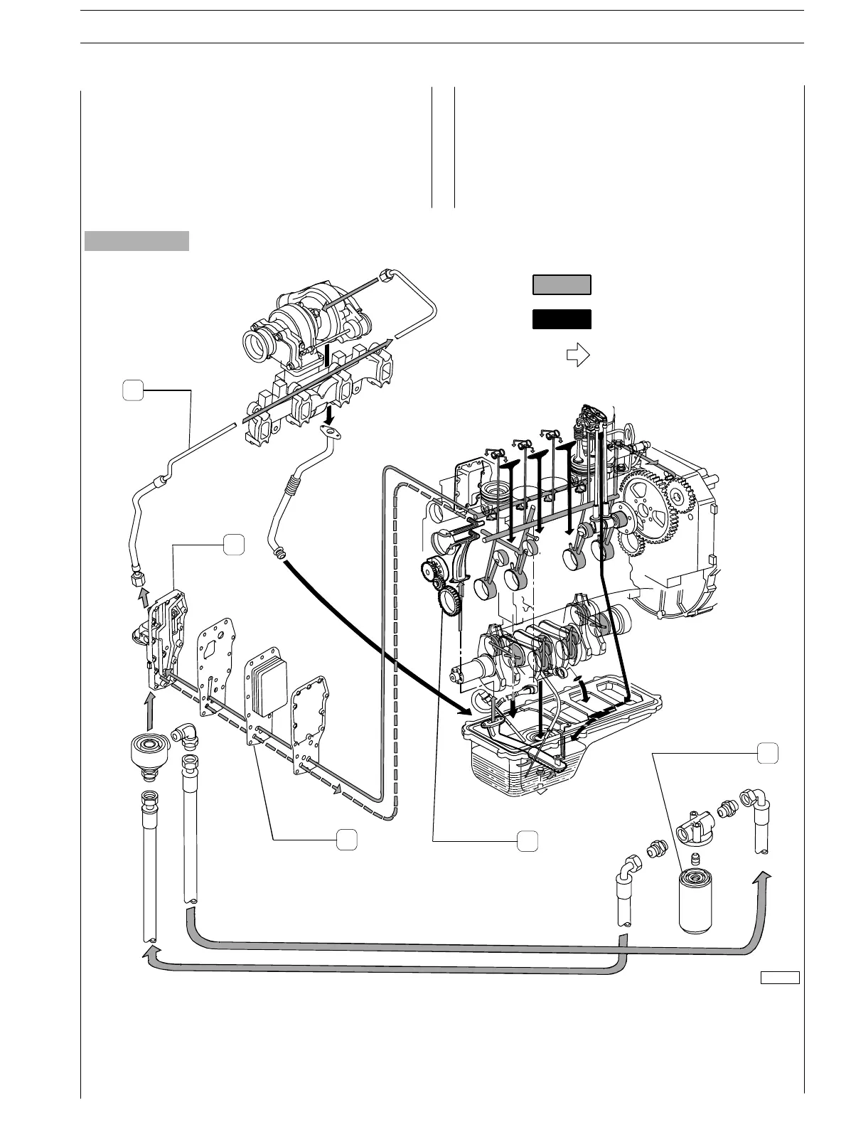
Lubrication by forced circulation is achieved through oil
rotary expansion pump (4), plac ed in the front part of the
basement, driven by the str aight−tooth gear splined to the
shaft’s bar ho ld.
From the pan, t h e lubrication oil flows to the dr iving shaft, to
the camshaft and t o the valve drive.
LUBRICATION SYSTEM LAYOUT (4 c yl. engines)
Routing of oil under pressure
Routing of o il return by gravity
to sump
Introduction of oil
Lubrication involves the heat exchanger (2,3) as well, the
supercharged (through pipe 1) and the eventual c ompressor
for any eventual compressed air system.
All these components may often vary according to the
specific duty.
1
2
3
4
5
1. Lubrication oil pipe to supercharger − 2. Heat exchanger body − 3. Heat exchanger − 4. Oil rotary expansion pump −
5. Oil filter
E NG I NE S SECTION 1−GENERAL SPECIFICATIONS 5
ED. FEBUARY 2003
LUBRICATION