Figure 71
Figure 72
- Tighten the screws (2) to the prescribed couple and
assemble water temperature sen sor (1).
!
In order carry out a quicker adjustment of the
working slack between rocker arms and valves,
proceed as following:
Rotate the engine drive shaft, balance the valves of
cylin der 1 and adjust the valves identified by star
symbol, as indicated in the following table:
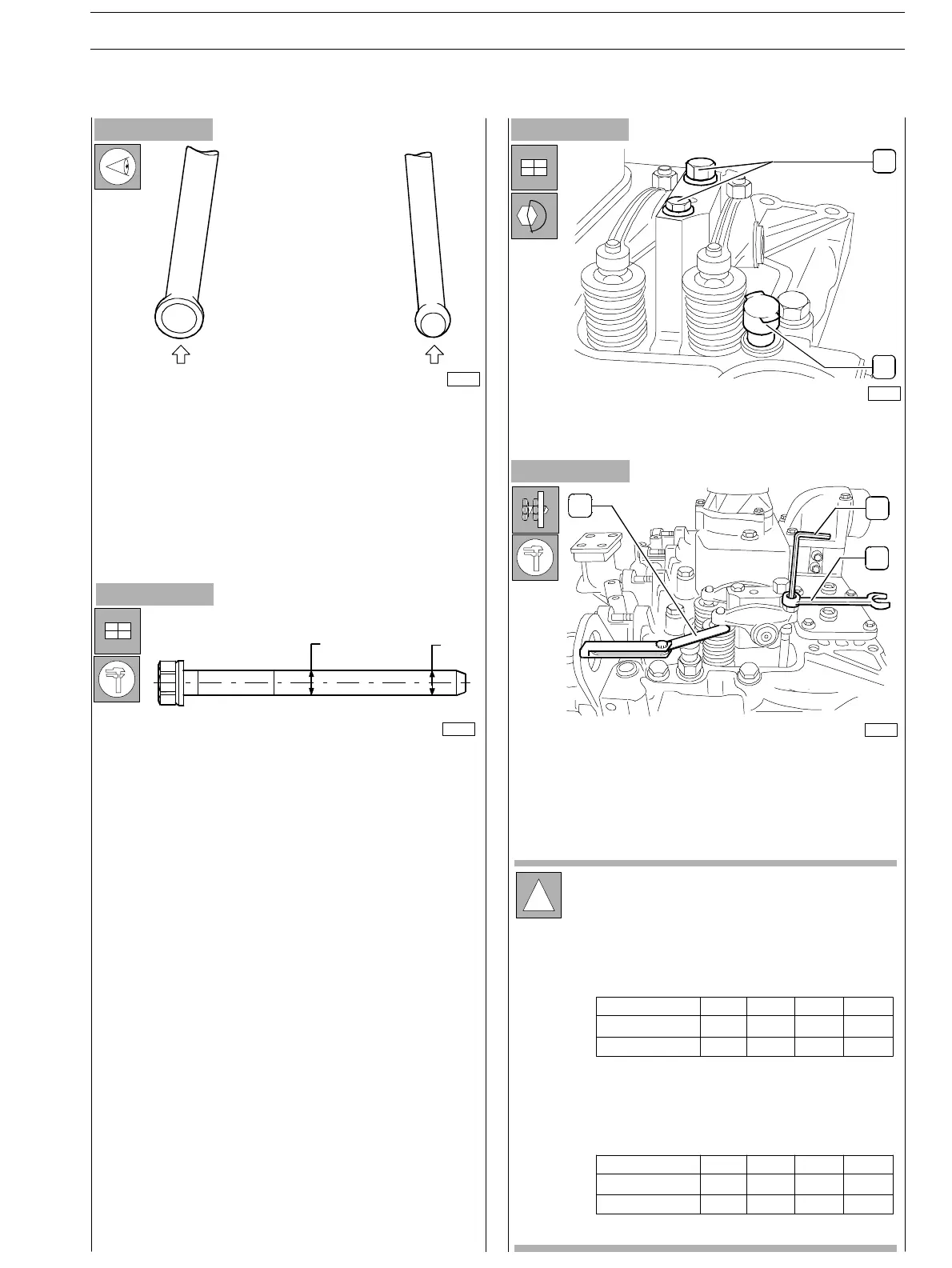
Before executing assembly, check the Rocker Arm driving
rods: these shall not be deformed; the spherical ends in
contact with the Rocker Arm adjustment screw and with the
tappet (arrows) shall not present evidence of seizure or
wear: in case of detection proceed replacing them.
The rods driving the suction and exhau st valves are identical
and therefore interchangeable.
Figure 73
Adjust the slack between rocker arms and valves using socket
wrench (1), point wren ch (3) and feeler gauge (2).
Correct working slack is:
− suction valves 0.30 0.05 mm
− exhaust valves 0.55 0.05 mm.
Figure 74
32655
D1D2
75703
- Insert the tappet driving rods and the Rocker Arm unit.
Before usin g the fixing screws again, measure them twice
as indicated in the picture, checking D1 and D2
diameters:
if D1 − D2 < 0,1 mm the screw can be utilised again;
if D1 − D2 > 0,1 mm the screw must be replaced;
1
2
75683
75806
2
1
3
Cylinder n°
Suction
Exhaust
1
234
−
*
**
*
−
−−
Cylinder n
Suction
Exhaust
1
234
−
*
**
*
−
−
−
Rotate th e engine drive shaft of 360 deg., balance the
valves of cy linder 4 and adjust the valves identified by
star sy mbol, as indicated in the following table:
SECTION 3 − DUTY − INDUSTRIAL APPLICATION E NG I NE S
27
ED. FEBUARY 2003