Figure 75
Figure 76
- Assemble injec t ors after having replaced the sealing
gasket (1).
!
Always replace the gasket s us ing new ones.
Check the threads of the fixing screws: there shall be
no evidence of wear or dirt deposit.
Seal n o ds shall have no visible deformation. In such
case provide for replacement with new nods.
Figure 77
- Assemble cylinder covers (2) with the respective gaskets;
- Fit the seal nods and tighten the screws fixing them to
the prescribed couple.
!
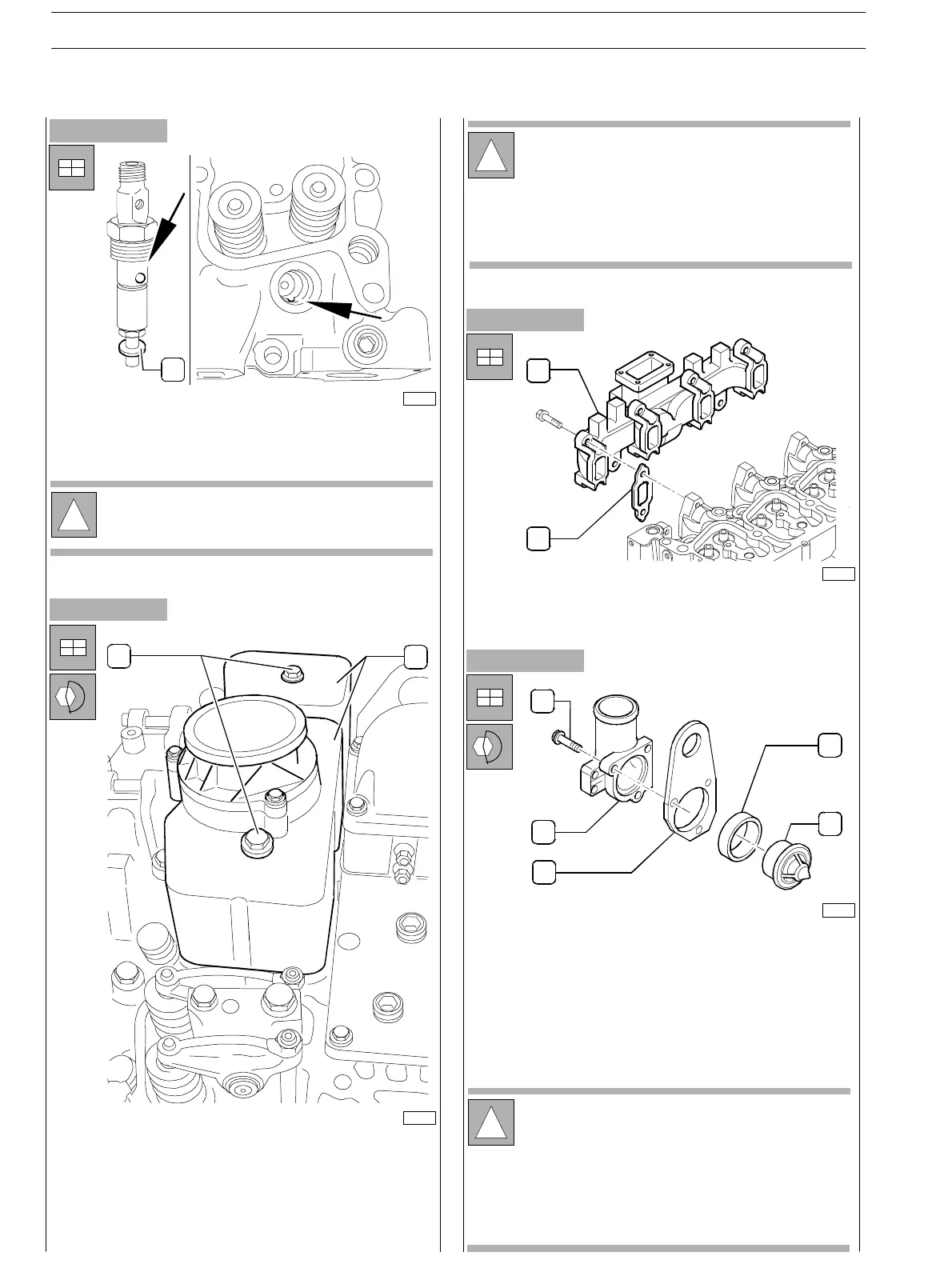
Figure 78
- Assemble exhaust manifold (1) providing new gaskets
(2).
- Assemble thermostat unit (2) including thermostat (5)
and gasket (4).
- Tighten the screws to the prescribed couple.
1
75707
75808
!
Dur ing assembly of injec tors, verify that the injector
sphere is correctly positioned on the head housing.
75681
1
2
1
2
1
2
3
4
5
75685
The sc rews (1) have been have been utilised to fix
the bracket (3).
Disassemble the bracket and reassemble
components from 1 to 5 as shown in the picture.
The gasket must be new.
SECTION 3 − DUTY − INDUSTRIAL APPLICATION
28
E NG I NE S
ED. FEBUARY 2003
zs