Figure 84
Figure 85
75679
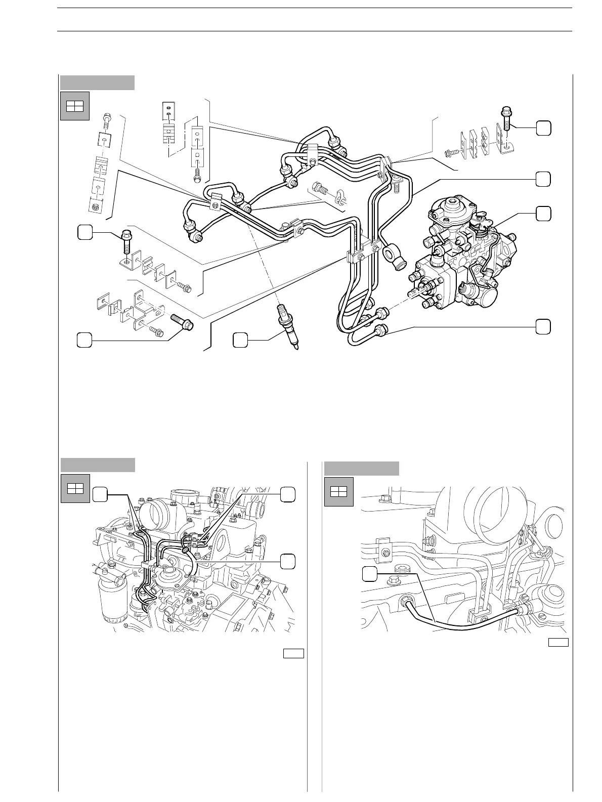
- Assemble the pipes (1) and (2) providing fuel feed and
recov ery between pump and injectors;
Screw up the locking nuts and tighten the screws fixing
the fuel recovery manifold; fix the pipes to the injectors
throughout the brackets previously assembled.
Figure 86
- Fix the LDA pipeline (1) to the engine head and to the
feed pump.
7
6
5
1
2
3
4
1. Rear bracket fixing screw (on suction collector plate) − 2. Fuel recovery pipeline to pump − 3. Rotary feed pump − 4.
Connection nut to pumping elements − 5. Injecto r − 6. Bracket fixing screw to injection pump side− 7. Front bracket fixing
screw (on suction collector plate)
1
1
2
1
75677
SECTION 3 − DUTY − INDUSTRIAL APPLICATION E NG I NE S
31
ED. FEBUARY 2003
zs