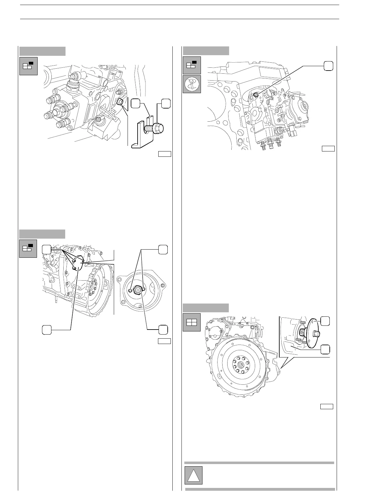
Figure 96
- Part ially loosen the lateral sc rew (2) loc king the pump
shaft and remove the slip washer (2). Absolutely keep
the slip wash er (it is recommended to fix it with stripe
or wire to the pump).
- Tighten the lateral screw (1) blocking rotation of the
pump shaft.
Figure 97
- From the pump side, loosen the fixing nuts (1) without
removing them in order to enable moving the pump
backwards using 380000979 extractor.
-
Assemble the 380000979 extractor throughout the two
threaded ports (4, Figure 97) and wit hdraw the gear
from the pump shaft.
- Proper ly h old the feed pump and loosen c ompletely the
fixing nuts.
- Withdraw the pump from the studs, together with the
gasket.
Figure 98
- From timing side, remove the cover (2) loosening the
screws (1) in order to have access to the union fixing nut
(3) to the pump driving gear.
- Loosen the fixing nut (3) and remove the relating washer.
When assembling the feed pump to the engine, it is n ecessary
to meet the P.M.S. requirements for the N.I. cylinder.
-
Use the 380000988 tool (2) on the flywheel box (I)
to car ry out flywheel rotation and operate using the pin
as previously described.
Figure 99
!
Hold the pump driving gear to avoid interference or
cr awling during timing gear rotation.
75721
2
1
1
23
4
75693
1
75694
75714
1
2
SECTION 3 − DUTY − INDUSTRIAL APPLICATION
36
E NG I NE S
ED. FEBUARY 2003
zs