Figure 100
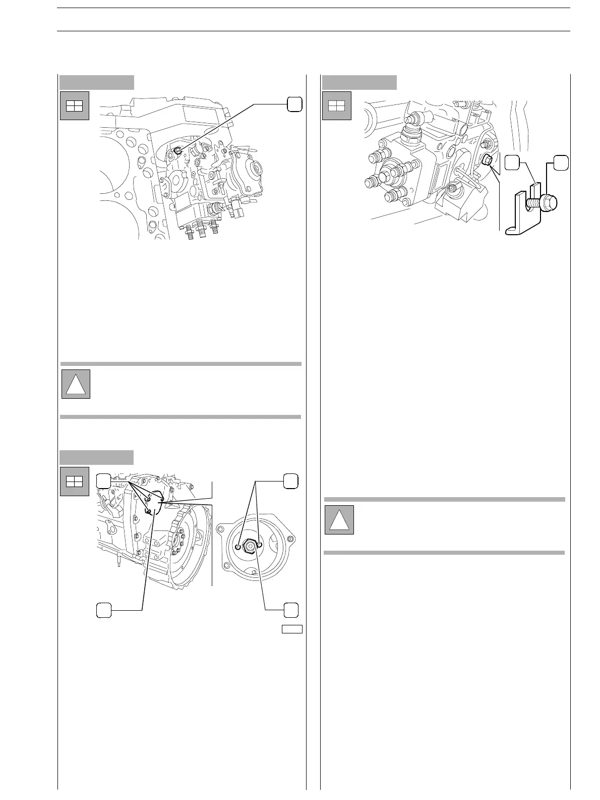
- Assemble the pump pre−set in its housing on the engine,
fitting the shaft into the gear port (not provided with
wrench).
- Tighten the fixing nuts (1) locking the pump flange in the
slot centre .
- Partially loosen the screw (2) locking the pump shaft
rotation and fit the slip washer (1). Tighten th e screw
fixing above s aid washer: this way the feed pump shaft
is free to rotate.
- Assemble the cover (2, Figure 101) including gasket and
tighten the screws (1,Figure101).
- Pull the pin outwards setting the camshaft gear free.
- Disassemble t h e 380000988 t o o l lo c kin g fly w h eel
rotation; place the starter in its housing.
- Connect all pipelines (from pumping elements to
injectors, bleeding recovery pipes from in jec t ors to
pump, LDA pipeline and feed provided by priming
pump).
- Connect electrical connections to electro−magnets on
the hydraulic head and on KKSB.
Figure 101
!
The gasket removed during pump disassembly shall
not be utilised again.
Always use original spare parts.
Figure 102
1
12
1
23
4
75715
- On th e timing side, throughout the specially appointed
port, fit the washer and screw up the fixing nut (3) to the
pump shaft. Lock the nut to the 90−95 Nm c o uple.
!
In case pump removal has been carried out while the
engine was assembled, connect acceleration cable.
SECTION 3 − DUTY − INDUSTRIAL APPLICATION E NG I NE S
37
ED. FEBUARY 2003
zs