Figure 119
Figure 120
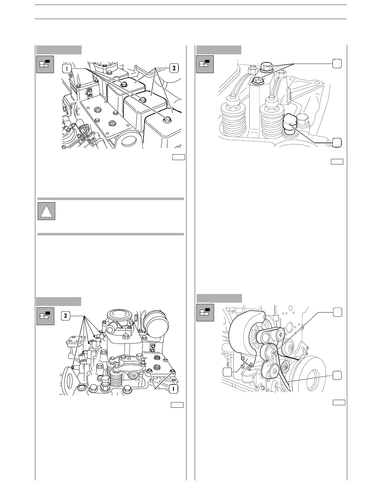
- Remove tappet caps:
Loosen the fixing screws (1) an d lift the caps (2);
remove the gaskets.
- Disassemble suction and exhaust manifolds: loosen the
screws (1) fixing t h e suction manifold plate to the
cylinder head (some of them have already been
screwed−out sinc e fixing the pipe brackets to th e
injectors); from the exhaust manifold side loosen the
eight (2) fixing screws; remove t he gasket s .
- Disassemble rocker arm bearings; loosen the two fixing
screws (2) and remove the complete rocker arm bearing;
withdraw tappet rods. Repeat the operation for all the
remaining roc ker ar m bearings.
- Disassemble water temperature transmitter (1).
!
On the central cap there is a blow−by valve for the
lubrication oil vapours.
All the gaskets shall always be replaced durin g
assembly.
76149
76151
Figure 121
75683
1
2
Figure 122
74171
- Unloose the screws fixing the alternator’s protection to
thesupportandremoveit.
- Workon the drive belt tensor (1) and extract the belt (3)
from the belt pulleys, from the water pump ones and
from the belt rebound pulleys.
- Disassemble the belt tensor.
- Unloose the screw fixing the alternator to the upper
bracket.
2
3
1
SECTION 3 − DUTY − INDUSTRIAL APPLICATION E NG I NE S
43
ED. FEBUARY 2003
zs