Figure 123
Figure 124
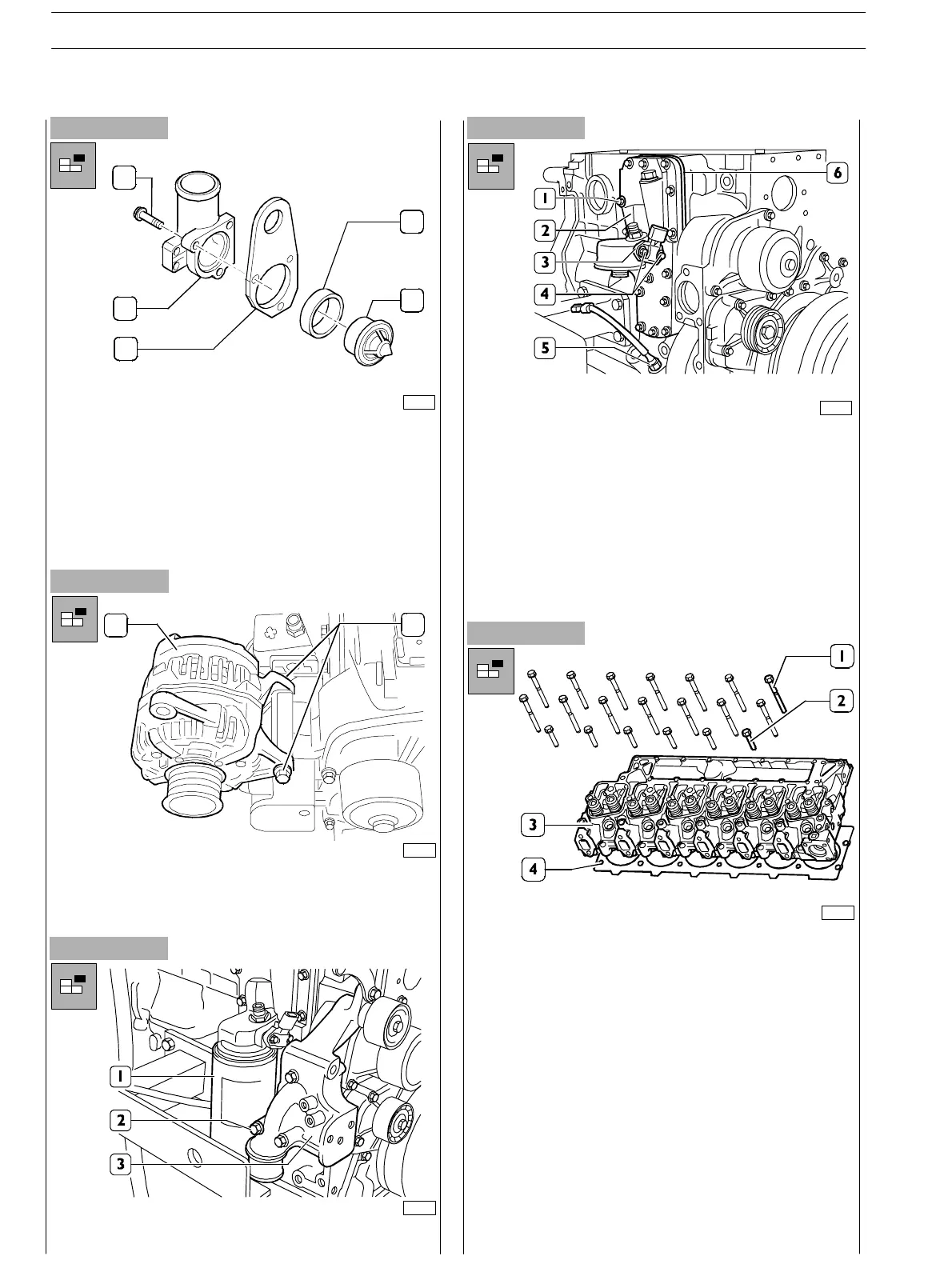
- Disassemble thermostat unit; loosen the three fixing
screws (1) and disassemble the t hermostat unit (2)
together with the bracket (3); remove the gasket (4) and
the thermostat (5).
- Assemble the bracket in th e original position fixing it with
the screws of the thermostat unit.
- Proper ly hold the alternator (1) separatin g it from its
bearing by loosening the screw (2); remove screw nut
and washer.
Figure 125
Figure 126
75685
1
2
3
4
5
1
2
75686
- Loosen the screws (2) and withdraw the alternator
bearing (1).
70141
- Loosen the screws (4) and disassemble the oil
pressure/temperature sensor (3) (if fitted).
- Loosen th e screws (1) an d disassemble the oil filter/heat
exchanger bearing (2), inter layer plate (6) and relating
gaskets.
- Disassemble oil level sensor (5) (whether provided).
- Disassemble injection pump (see specific procedure)
and the power take−off underneath.
Figure 127
76152
70140
- Disassemble cylinder head;
loosen the screws (1) and (2) fixing the cylinder head (3);
hook the brackets with metal ropes and, throughout a
hoist withdraw c ylinder head from th e block.
SECTION 3 − DUTY − INDUSTRIAL APPLICATION
44
E NG I NE S
ED. FEBUARY 2003
zs