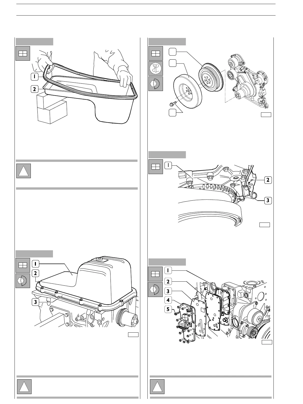
Figure 163
- Provide for new gasket replacement (1) of t he oil pan (2).
Figure 164
Figure 165
- Assemble the following elements to the block: new
gasket (1), heat exc hanger (2), new gasket (3), oil filter
bearing (4).
Tighten the screws (5) and lock them to the prescribed
couple.
- Assemble oil pan (1), apply the plate over it (2). Tighten
the screws (2) and lock them to the prescribed couple.
Figure 166
!
The pictures illustrating the pan and of the rose pipe
may not correspond to the ones of your model.
However the procedures described are applicable
anyway.
70154
!
Before assembly, always check that the threads of the
ports and of the screws have no evidence of tear and
wear nor dirt.
!
Before assembly, always check that the threads of the
ports and of the screws have no evidence of tear and
wear nor dirt.
1
2
3
74175
- Assemble the pulley (1) and the dumping flywheel (2) to
the driving shaft.
- Tighten the fixing screws (3) and clamp them to the
couple 68 ± 7 Nm.
70230
- Fit a new sealing rin g on t h e speed sensor (3) (if fitted).
- Fit the speed sensor (3) on the front c over (1) and
tighten the screw (2) to the specified torque (if fitted).
Figure 167
70231
SECTION 3 − DUTY − INDUSTRIAL APPLICATION
54
E NG I NE S
ED. FEBUARY 2003
zs