SECTION 58 -- ATTACHMENTS AND HEADERS -- CHAPTER 1
58-11
5. Press the bearing cones onto the input shaft, and
install the appropriate bearing cups into the
housing and cover. Do not install the seal into the
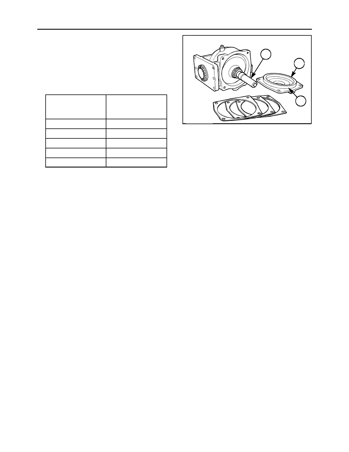
cover yet. Install the input shaft, 1, and cover, 2,
onto the gearbox, and shim (shim pack thickness
of 0.025″ is a good starting point) between the
housing to obtain the appropriate rolling torque
per the attached chart:
Output Shaft
orque
in. lbs (N⋅
⋅⋅
⋅m)
2 (0.23) 8-12 (0.9-1.36)
3 (0.34) 11-15 (1.24-1.69)
4 (0.45) 14-18 (1.58-2.03)
5 (0.56) 17-21 (1.92-2.37)
6 (0.68) 20-24 (2.26-2.71)
6. After setting the input shaft rolling torque, remove
the cover and install the shaft seal by driving it
into the bore until it seats against the shoulder in
the cover. Grease the seal lip liberally before re-
installing the cover. Apply silicone sealant to the
cover sealing flange, 3; reinstall the cover and
tighten the hardware.
600-4-14
1
2
3
22