SECTION 58 -- ATTACHMENTS AND HEADERS -- CHAPTER 2
58-32
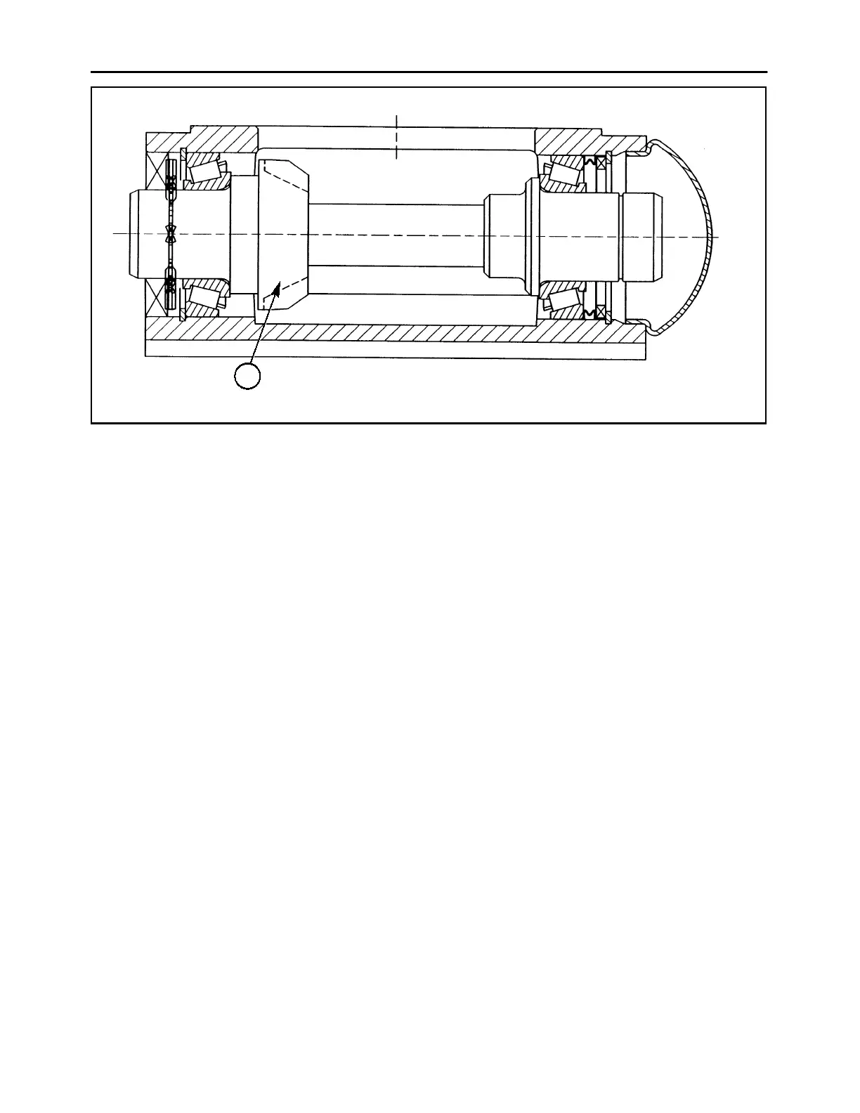
CUTAWAY VIEW FROM FRONT OF MODULE
1
75
DRIVE MODULE - ASSEMBLY
The drive module must be assembled with the pinion
gear, 1, positioned to the right side of the housing, as
viewed from the rear, in order to ensure the cutter bar
is driven in the correct direction. The drive module is
serviced using the same lower pinion kit as the disc
modules; all parts are fully interchangeable, but the
drive module does not use a slinger or seal on the left
end of the pinion shaft.
The backlash between the pinion gear and the bevel
gear on the output shaft of the bevel gearbox is con-
trolled by the precision machining of the drive module
and bevel gearbox housings, the use of precision
forged gears, and the use of low tolerance bearings,
which are manufactured to provide a specific “stack
height”, or combined thickness. It is not necessary to
check the backlash of the gearset after the bevel
gearbox is reassembled onto the drive module.
NOTE: The low tolerance bearings are manufac-
tured for a specific “stack height”. Do not mix old and
new bearing components or substitute with “jobber”
bearings.