SECTION 31 -- IMPLEMENT POWER TAKE-OFF -- CHAPTER 1
31-9
U-JOINTS - DISASSEMBLY
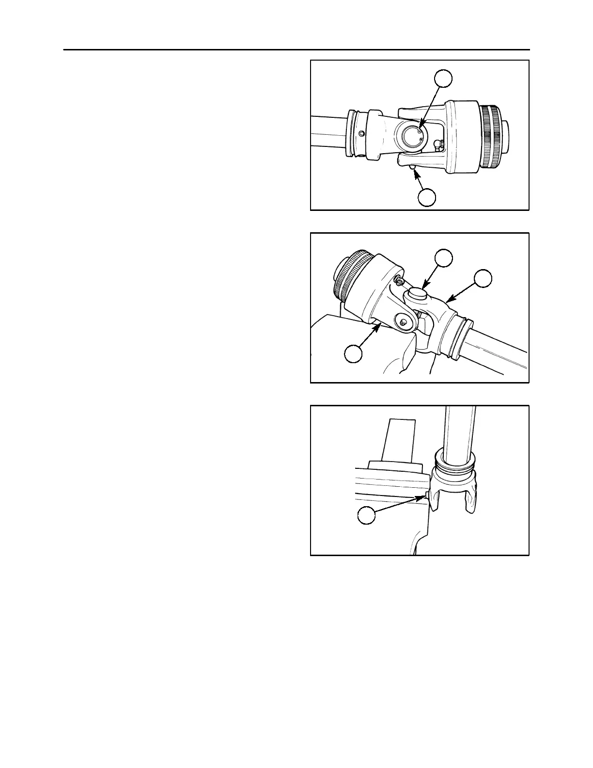
1. Remove the PTO shaft from the unit, and remove
the shielding, as previously described. Remove
the internal snap rings, 1, from the yoke ears, and
remove the grease zerk, 2, from the bearing cup.
600-3-21
1
2
21
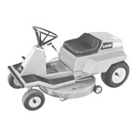
2. Position the U-joint assembly in an open vise as
shown, with each ear of one yoke, 1, supported
byavisejaw.Withasoft-facedhammerormallet,
strike the top ear of the unsupported yoke, 2; this
will drive the top bearing cup, 3, outwards
approximately 1/4″ (8 mm).
600-3-22
1
2
3
22
3. Grip the loosened bearing, 1, in the vise, and
drive the yoke off the bearing by striking the yoke
ear with the soft-faced hammer or mallet.
4. Repeat the process to remove the bearing direct-
ly opposite the one just removed, after which the
yoke itself may be removed.
5. To remove the two remaining bearings and the
cross, support the cross in the vise, making cer-
tainthevisejawsarecoveredwithbrassprotec-
tors. By striking the yoke ear, the bearings can be
removed in the same manner as described in
steps 2 & 3.
600-3-23
1
23