SECTION 31 -- IMPLEMENT POWER TAKE-OFF -- CHAPTER 1
31-10
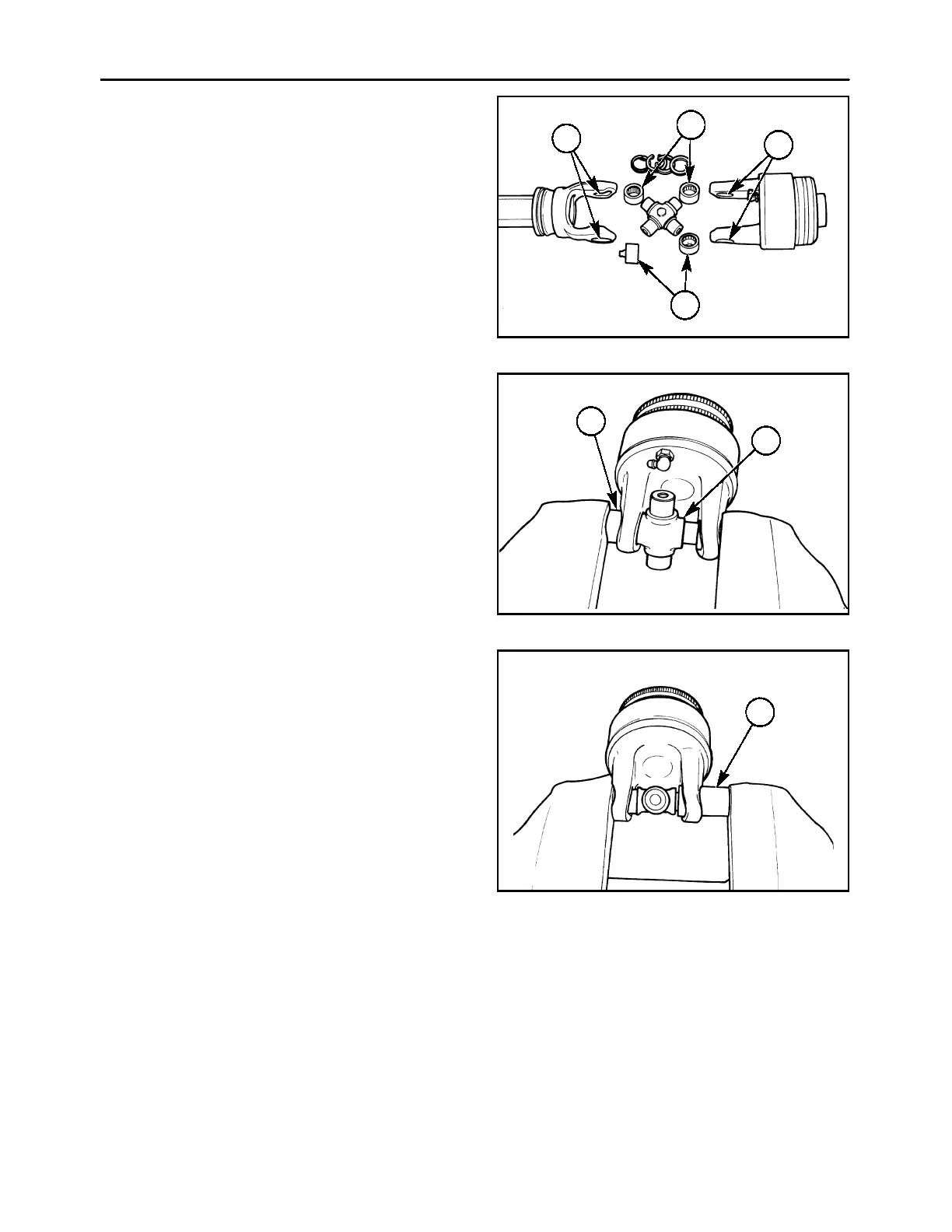
U-JOINTS - INSPECTION
NOTE: The U-joint cross and bearings should be re-
placed any time the U-joint is disassembled, even if
the cross and bearings were not the source of failure.
1. Inspect the yoke ears, 1, for wear in the bearing
area; replace the yoke if there is any evidence of
wear, or if the bearing area is distorted. The bear-
ings, 2, must be a tight fit in the yoke ear.
600-3-24
1
1
2
2
24
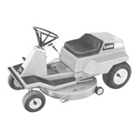
U-JOINTS - ASSEMBLY
1. To reassemble the U-joint, start one bearing, 1,
into the yoke ear, and position the center cross,
2, through the yoke. Clamp the yoke assembly in
a vise, and carefully use the vise to press the
bearing cup into the yoke ear as far as possible.
Remove the yoke from the vise, and start the se-
cond bearing cup into the opposite yoke ear. Re-
position the assembly in the vise, and press the
second bearing in as far as possible. Pivot the
cross while pressing the bearings in to check
proper bearing alignment.
600-3-25
1
2
25
2. Loosen the vise, and position a bushing driver, 1,
or a socket of a similar size as the bearing against
one bearing. Use the vise to press the one bear-
ing in past the snap ring groove. Remove the
yoke from the vise, and install the snap ring in its
groove. Reposition the yoke in the vise, and use
the socket or driver to press the opposite bearing
in until its retaining snap ring can be installed.
NOTE: It may be difficult to rotate the cross after
seating the second bearing. This condition will be
corrected after complete assembly of the U-joint.
600-3-26
1
26