SECTION 58 -- ATTACHMENTS AND HEADERS -- CHAPTER 1
58-12
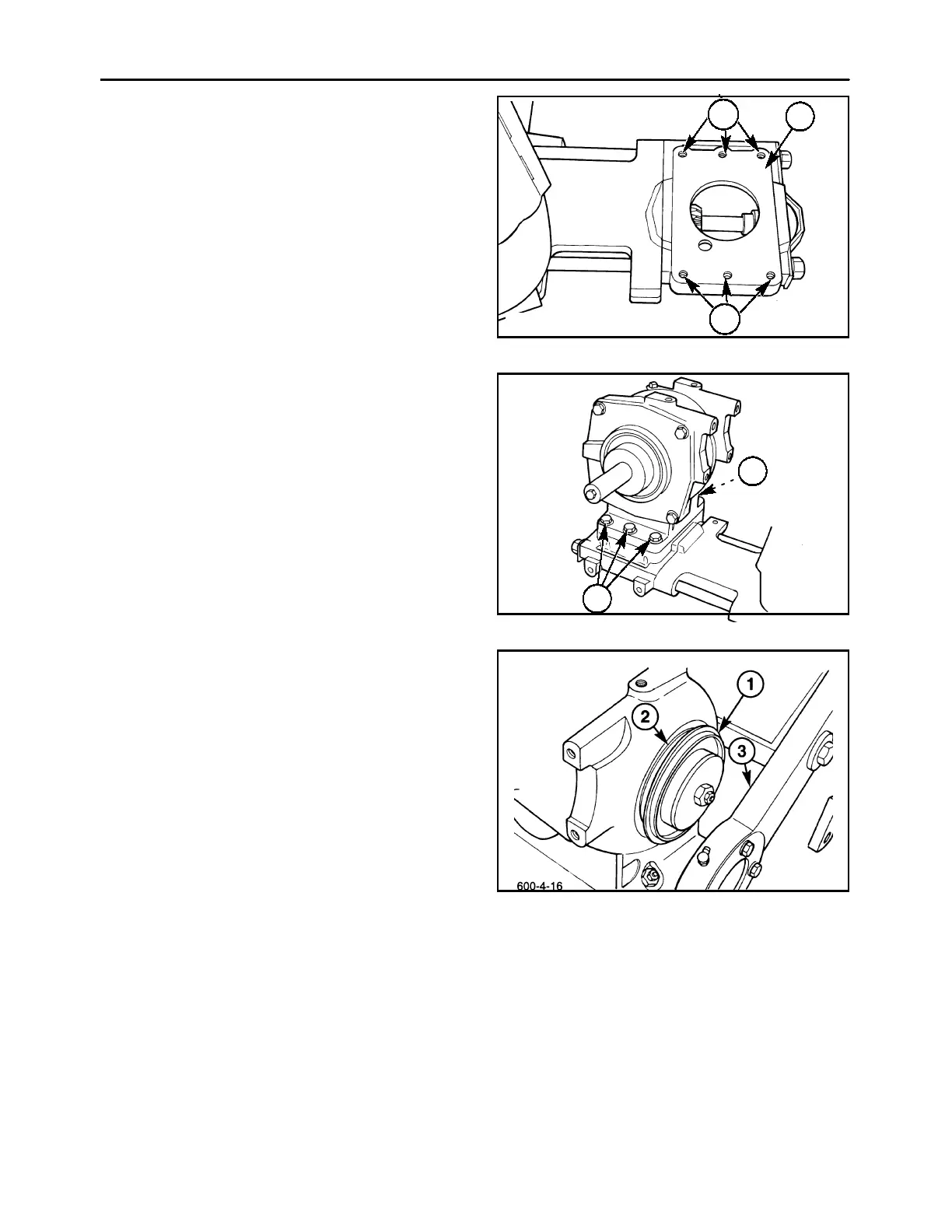
INSTALLATION
1. Thoroughly clean all sealant residue off of the
mounting surface, 1, on the drive module, and
apply a thin coat of sealant to the entire surface.
NOTE: If the mouning holes, 2, for the gearbox are
elongated, the drive module should be replaced.
600-4-15
1
2
2
23
2. Carefully set the bevel gearbox down onto the
drive module, ensuring that the pilot shoulder fits
into the bore on the drive module, and the gears
mesh together. Align the bolt holes, and install
the six 1/2″ Grade 8 cap screws, 1. Torque the
rear bolts to 117 ft lbs (159 N⋅ m); do not com-
pletely tighten the front bolts at this time, as they
will be removed later for skid shoe installation.
600-4-7
1
1
24
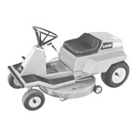
3. Apply grease to the black plastic “T-seal” washer,
1, and slide it onto the front pivot hub on the gear-
box, so that it engages in the groove, 2, on the
face of the gearbox. Slide the cutter bar assem-
bly together with the lift arm so that the front pivot
arm, 3, slides over the pivot hub on the gearbox,
and the groove in the pivot arm fits over the “T-
seal” washer.
25