SECTION 31 -- IMPLEMENT POWER TAKE-OFF -- CHAPTER 1
31-11
3. Position the second yoke over the cross, and
install the bearings using the same process de-
scribed in steps 1 & 2.
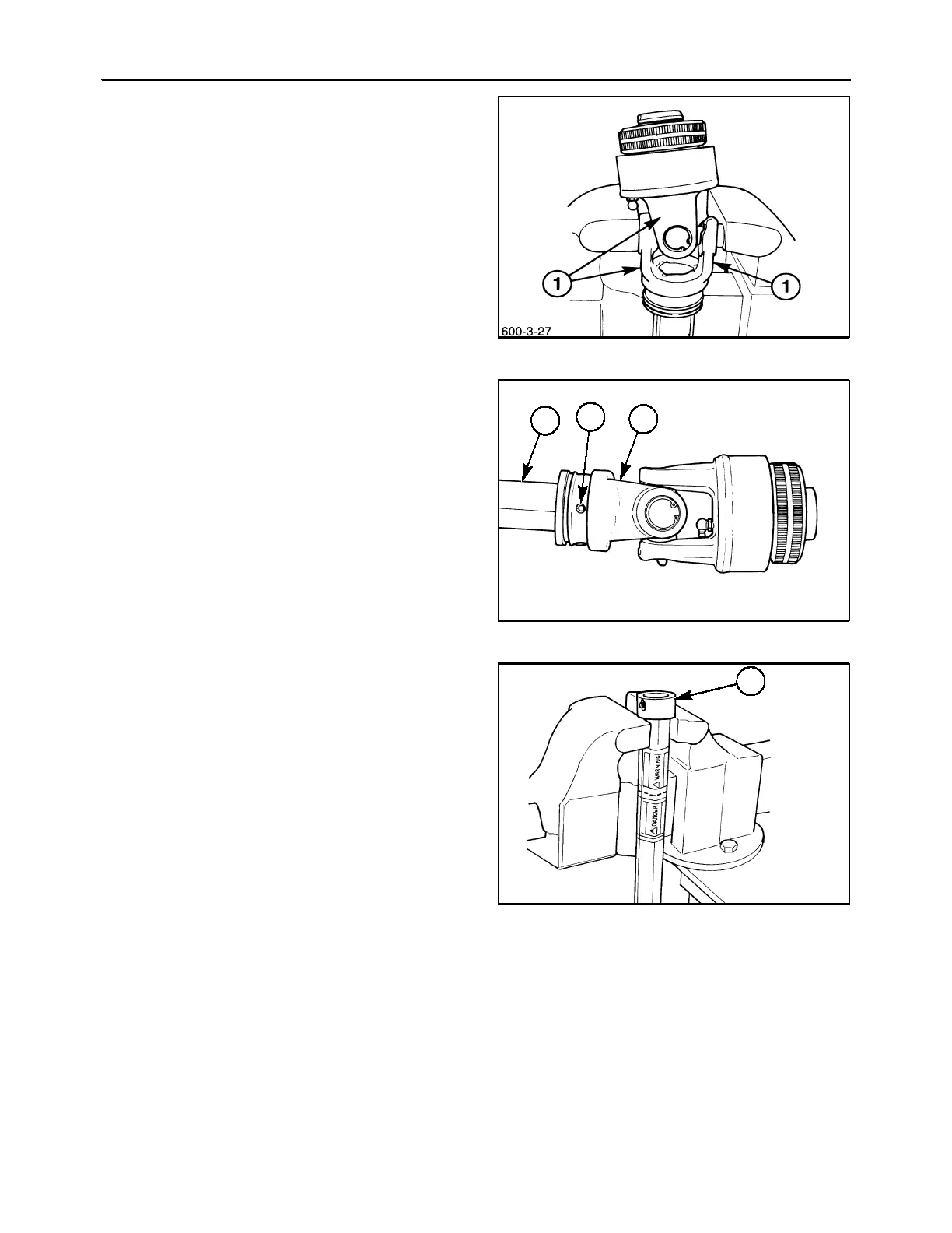
4. After complete assembly of the U-joint, strike the
forged surfaces, 1, of all yoke ears with a sharp
blow from a hammer. This will unspring the yoke
ears, and ensure proper seating of the bearings
to eliminate any tightness and ensure a free flex-
ing joint.
IMPORTANT: Use caution not to strike the bearing
bore area of the yoke ears, as this will damage the
bore and may cause premature cross bearing failure.
5. Reinstall the shielding as previously described.
27
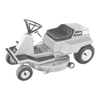
PTO SHAFT TUBE REPLACEMENT
1. Remove the PTO shaft from the unit, and remove
the shielding, as previously described. Using a
punch of appropriate size, drive the spring pin, 1,
out of the yoke. The tube, 2, may now be re-
moved from the yoke, 3. Install the new tube in
the yoke, and drive the spring pin through the
yoke and tube to secure them together.
NOTE: It may be necessary to cut the replacement
tube to match the length of the failed tube, in order to
adapt the driveshaft to the tractor the disc mower is
mounted on. Refer to Section 1 “General Informa-
tion” in this manual for information on matching the
PTO shaft to the tractor.
600-3-21
1
3
2
28
2. On the female tube section of the MDX71/81
driveshaft, a plastic grease bushing, 1, must be
removed and installed on the new tube. Remove
the bushing by positioning the shaft loosely in a
vise, and pull sharply downwards to pop the
grease bushing off the tube.
600-3-28
1
29