SECTION 35 -- HYDRAULIC SYSTEM -- CHAPTER 1
35-4
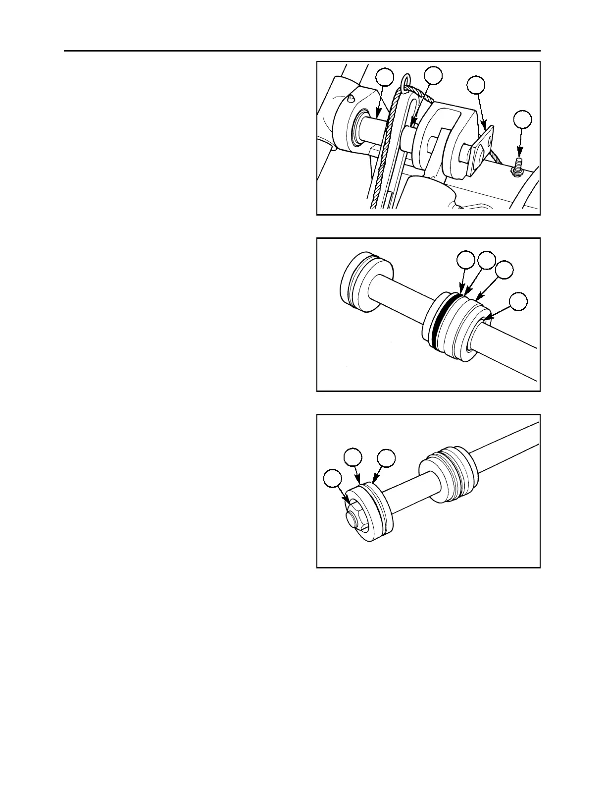
3. Inspect the cylinder barrel for damage to the bore
surface. If necessary, remove the cylinder barrel
from the unit and wash out any contamination.
To remove the cylinder barrel, remove the retain-
ing cap screw, 1, and slide the pin, 2, out of the
casting. Note the position of the two spacers on
either side of the stop rod; the long spacer, 3, is
on the rear with the short spacer, 4, to the front.
600-6-4
1
2
4
3
5
ASSEMBLY
1. Lubricate all seals and sliding surfaces before
assembly.
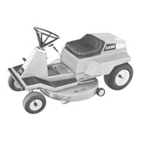
2. Install a new back-up washer and O ring in the in-
ner bore of the cylinder head, 1, with the back-up
washer towards the outer face. Drive a new wiper
seal, 2, into the outer face of the cylinder head.
Install a back-up washer, 3, and O ring, 4, into the
outer groove in the cylinder head, with the back-
up washer towards the outer face. Slide the new
retaining ring and the cylinder head assembly
over the piston rod.
600-6-5
1
2
4
3
6
3. Install a new seal, 1, on the piston, 2. Install the
piston with the recessed end facing outwards.
Install the locknut, 3, and torque it to 120 - 130 ft
lbs (163 - 176 N⋅m).
600-6-6
1
3
2
7