SECTION 58 -- ATTACHMENTS AND HEADERS -- CHAPTER 2
58-3
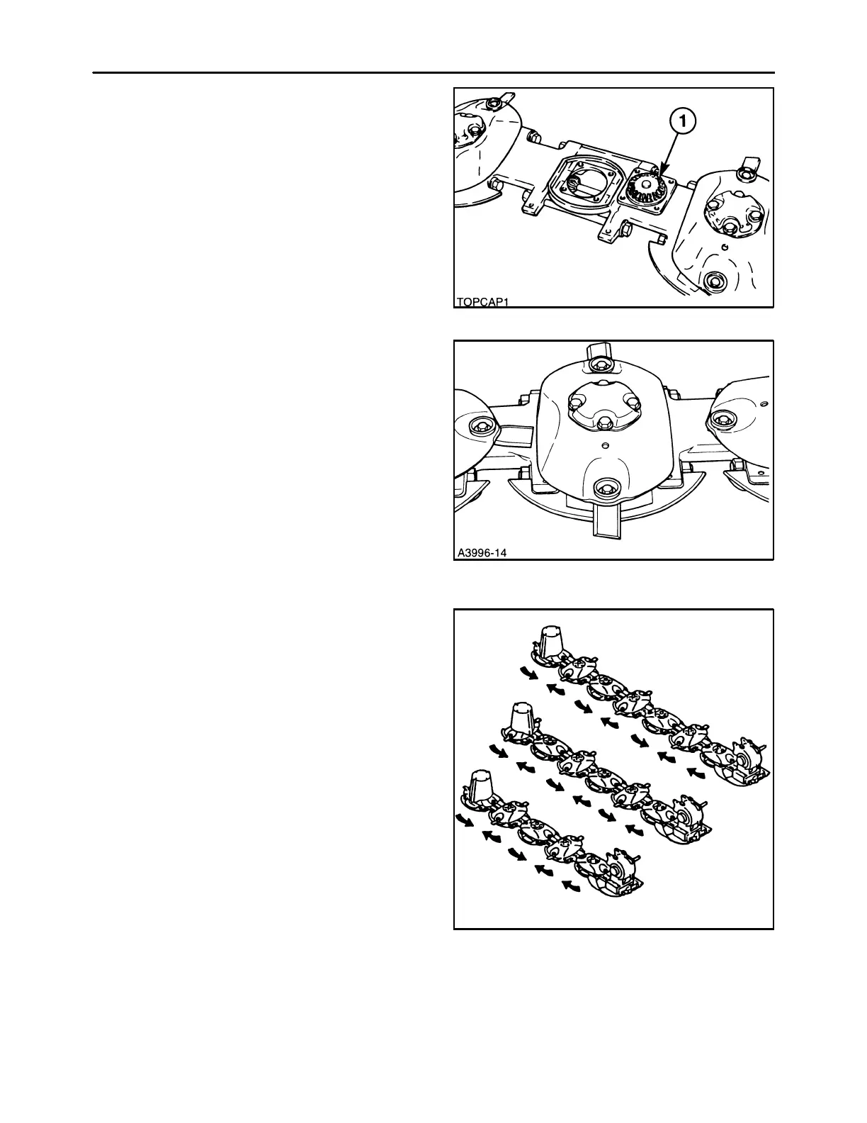
If a problem is found with a specific module, the ex-
tent of the damage can be quickly determined by re-
moving the disc and the top cap assembly, 1, of the
affected module. If damage is limited to the top cap
assembly components, the lower module can be
flushed out to remove contaminants, and a new top
cap assembly installed to complete the repair.
3
The cutterbar uses small diameter, high profile discs,
which are 3/16″ and hardened for long wear. The pro-
file of the discs provides a natural lifting action, which
helps fluff the cut crop for faster drying.
The discs are equipped with 2 inch wide knives,
which are retained with 1/2″ bolts and hardened knife
nuts. The knives are reversible for long life, and al-
ways have the beveled edge up. An arrow is stamped
on both sides of the knife to show the direction of rota-
tion.
Heat treated knife bolt protectors serve as a wear
surface to guard the bolt from deterioration, and can
be rotated to extend life. The knives can be easily
changed in any position on the cutterbar.
4
Each disc module is protected by a hardened ductile
iron rock guard and a skid shoe.
Skid shoes are 1/4″ thick and 8″ wide; they extend
behind the module several inches for optimum flota-
tion and extended wear life of the shoe.
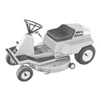
All cutterbar components are interchangeable be-
tween the disc mowers. The MDX71 and MDX91 disc
mowers, because of the odd number of discs and the
need for the end discs to be spinning inwards, have
the #1 and #2 discs co-rotating; that is, they both spin
in the same direction. This requires a slightly longer
spacer and driveshaft between the #1 and #2 disc
modules to eliminate interference between the
knives on these two discs.
MDX71
MDX81
MDX91
5