SECTION 58 -- ATTACHMENTS AND HEADERS -- CHAPTER 2
58-23
6. Apply grease to the sealing lip on the shaft seal,
and press them into place on each side of the
housing.
NOTE: The seal must be pressed into place with a
seal installing tool or suitable substitute. The seals
must be flush with the side of the housing, and square
to the shaft. If the seal is driven in with a hammer, it
will be distorted and leak, causing disc module
failure.
50
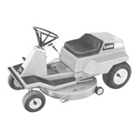
7. Apply silicone sealant to the threads of the drain
plug and check plug, and install them into the
housing. Pour 300 ml of API GL5 80W90 gear oil
through the top opening into the lower module.
51
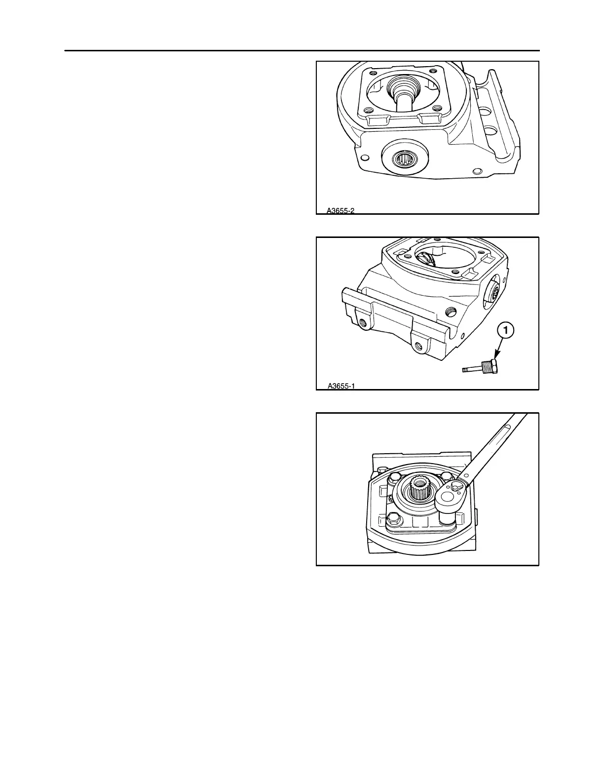
8. Apply a thin bead of silicone sealant to the seal-
ing flange of the new top cap assembly, and posi-
tion it on the lower module assembly with the
breather facing to the right. Apply silicone sealant
to the end of the threads of the top cap retaining
bolts, install them and torque to 83 ft lbs (113
N⋅m).
Do not install the disc hub onto the top cap at this
time, unless it is desired to check backlash. To
check backlash, the disc hub must be installed
and torqued to 150 ft. lbs. (224 N⋅m) to seat bevel
shaft against bearings and housing.
Acceptable backlash is 0.005″ to 0.011″. If back-
lash is unacceptable, recheck assembly of the
disc module.
19985741
52