SECTION 58 -- ATTACHMENTS AND HEADERS -- CHAPTER 2
58-29
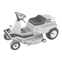
Apply a locking compound to the threads, and
install the three cap screws, 1, to secure the rear
of the bevel gearbox to the drive module. T ighten
the cap screws snugly, but do not torque at this
time.
600-4-1
1
66
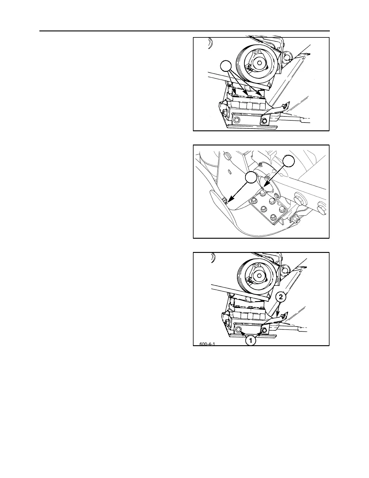
8. Slide the front lip of the inner skid shoe, 3, on over
the front of the bevel gearbox and drive module.
Apply a locking compound to the threads, and re-
install the three cap screws, 1, but do not tighten
at this time. Position the inner shield, 4, between
the #1 disc and the canopy support. Attach the in-
ner shield and pipe support to the front of the skid
shoe using a carriage bolt, 2, and flange nut.
19990604
1
2
67
9. Install the two cap screws, 1, and lock washers
to secure the rear of the inner skid shoe to the
drive module; position the inner shield mounting
bracket, 2, under the right cap screw. Tighten the
two rear cap screws, 1, to 83 ft lbs (113 N⋅m). Af-
ter the two rear cap screws are tightened, torque
the three front cap screws, 1, Figure 66, and the
three rear cap screws, 3, to 117 ft lbs (159 N⋅m).
10. Complete tightening of the tie bolts to 50 ft lbs
and 1-1/2 turns of torque, if this was not finished
previously.
68