Chapter 7 – PID Control
CHAPTER 7 - PID CONTROL WIRING AND BLOCK DIAGRAM
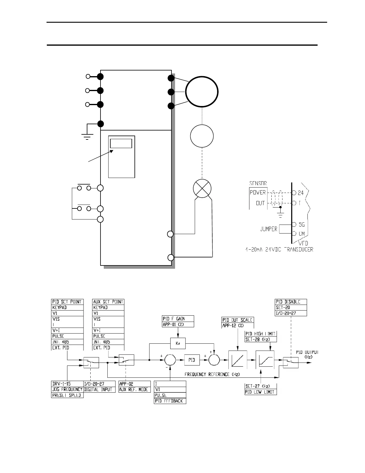
7.1 VFD Wiring for PID Control
The keypad is normally used
for PID set-point adjustment.
Any digital input can be
programmed for Open-Loop
function, which allows to
disable PID and control VFD
in standard V/F mode. The
feedback transducer can be
fed by 12VDC or 24VDC
internal VFD power supplies.
If 24VDC is used on VFD up
to 40HP, connect CM
terminal to 5G as shown on
below diagram.
7.2 PID Control Block Diagram
The picture above shows a PID block diagram with most of the required PID operation parameters. The PID
output (Target) and VFD output frequency (Out) can be viewed on the same screen in parameter DRV-25.
Power
Input
Pressure
Set-point
M7
FWD Run/Stop
M1
(Setting: Open-loop)
+12VDC Power
Feedback Signal
I
VFD PID Control
G
W
V
U
Output
+
Transducer
MOTOR
PUMP
R(L1)
S(L2)
T(L3)
Keypad