Chapter 9 - Options
9-6
9.9 Dynamic Braking Resistor Sizing
When dynamic braking is required for the application, the dynamic braking resistor should be sized based
on the table below. Determine an ED (Enable Duty) cycle and continuous braking time and select proper
resistor values. If ED is increased from 5% to 10%, the DB resistor Wattage rating should be doubled.
Selecting resistor with Ohms values less than values shown in the table below can create over current and
overheat faults and even damage DBU IGBT transistors. Decreasing the resistor wattage can create
overheat conditions for resistor and even damage it.
Motor Size
(kW / HP)
Enable Duty/ Braking
Time
100 % Braking Torque 150% Braking Torque
230V
18.5 / 25 5% / 15 sec 9 2400 5 3600
22 / 30 5% / 15 sec 8 2800 5 3600
30 / 40 10% / 6 sec 4.2 6400 - -
480V
7.5 / 10 5% / 15 sec 90 1000 60 1200
22 / 30 5% / 15 sec 30 2800 20 3600
37 / 50 10% / 6 sec 16.9 6400 - -
45 / 60 10% / 6 sec 11.4 9600 - -
55 / 75 10% / 6 sec 11.4 9600 - -
75 / 100 10% / 6 sec 8.4 12800 - -
90 / 125 10% / 6 sec 8.4 12800 - -
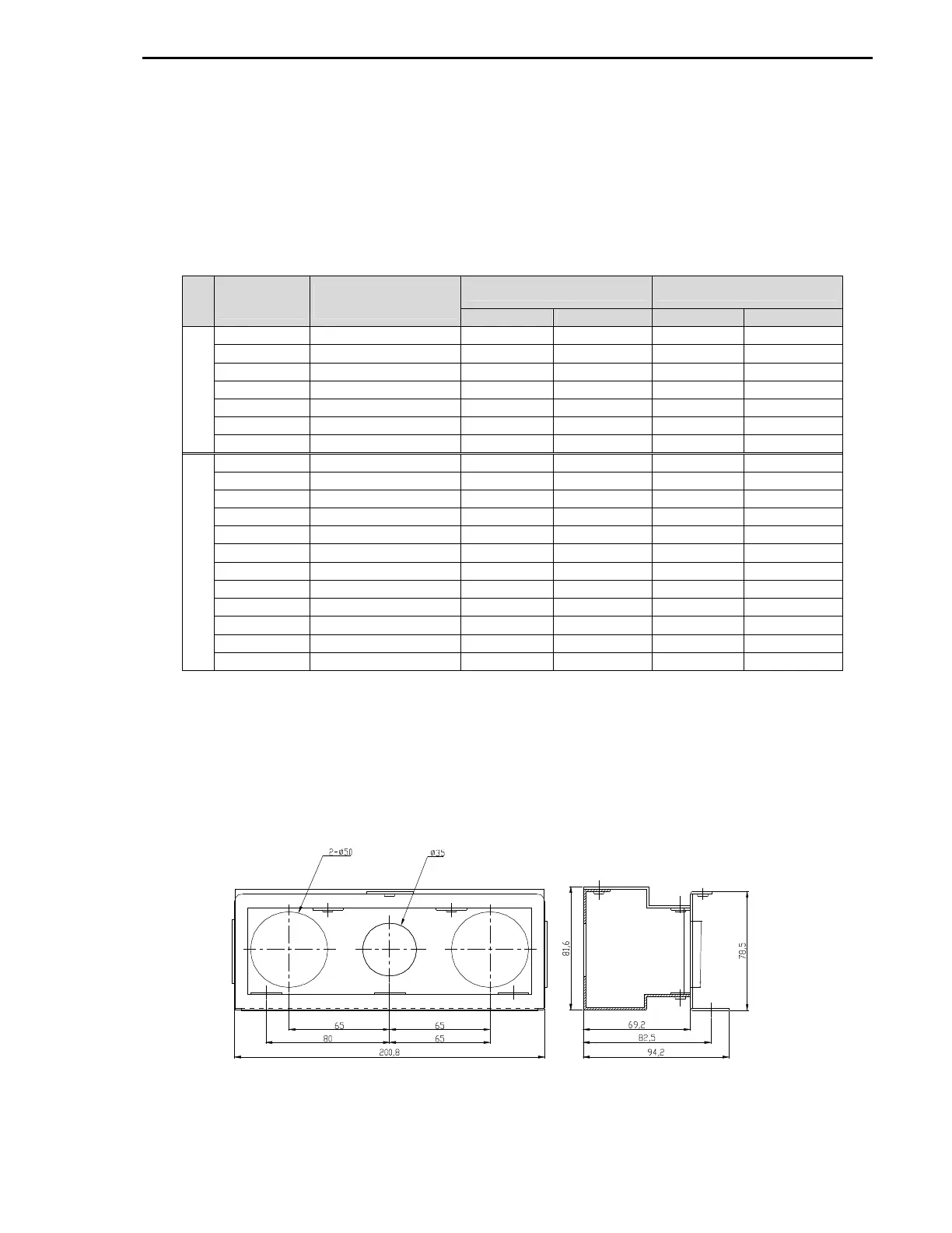
9.10 NEMA TYPE 1 Optional Conduit Box
The NEMA TYPE 1 Conduit Box is required if VFD is installed on the wall to meet NEMA 1
rating.
Remove the metal plate on the bottom of the VFD and install this kit using same screws.
[Conduit box for 020~025HP VFD]