Chapter 9 - Options
9-2
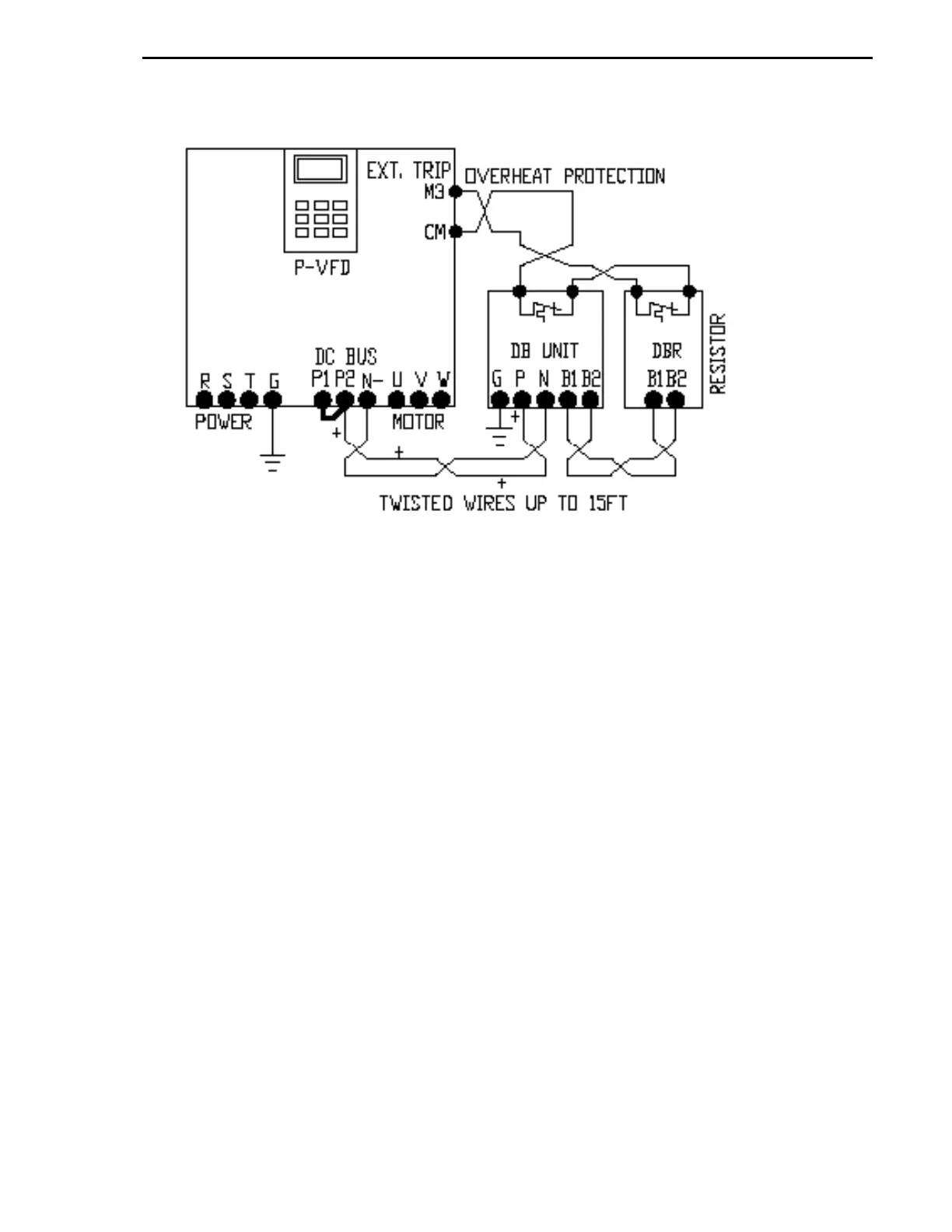
9.5 The basic wring diagram for Dynamic Braking Unit and Resistor.
Notes:
1. Use 600V rated twisted wires for DBU and DBR wiring.
2. If DBU overheat protection terminals are labeled CM and OH, this is an open collector
transistor output rated 100mA up to 30VDC and it will be closed when DBU trips on
overheat. In this case DBR thermostat and DBU overheat protection outputs cannot be wired
in series (one is normally open and another one is normally closed).
3. The multi-DBU configuration can be used for one VFD. Refer to DBU and DBR manuals for
wiring details.