Chapter 3 – Installation & Wiring
3.2 Basic Wiring Diagrams
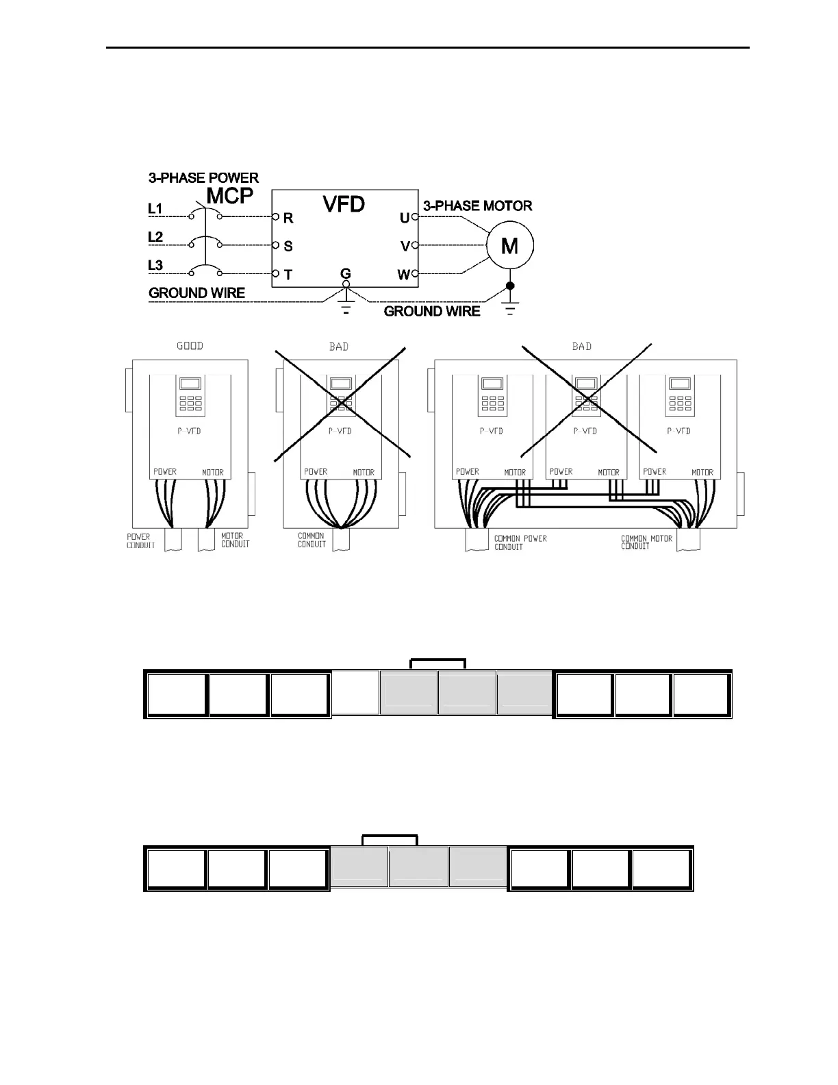
3.2.1 Power wiring diagrams
Basic Power wiring for 7.5~600HP (5.5~450kW) VFDs.
For single-phase power, connect L1 to R and L2 to S terminals.
VFD can malfunction or be damaged if motor and power wires are in the same conduit!
Power terminals for 7.5 ~ 40HP (200V/400V/600V) VFDs
R(L1)
S(L2)
T(L3)
G P1(+)
P2(+)
N(-) U V W
Power terminals for 50~125HP (400V/600V) VFDs
R(L1)
S(L2)
T(L3)
P1(+)
P2(+)
N(-) U V W
Notes: a) The Ground wire should be connected to the VFD ground terminal or chassis ground screw.
b) Do not connect any wires except dynamic braking unit to P1+, P2+ and N- terminals.
c) Do not remove the jumper between terminals P1+ & P2+ except for DC bus reactor wiring.
DC Bus Positive & Negative
DC Bus Positive & Negative