Chapter 5 – Parameter List
4-4
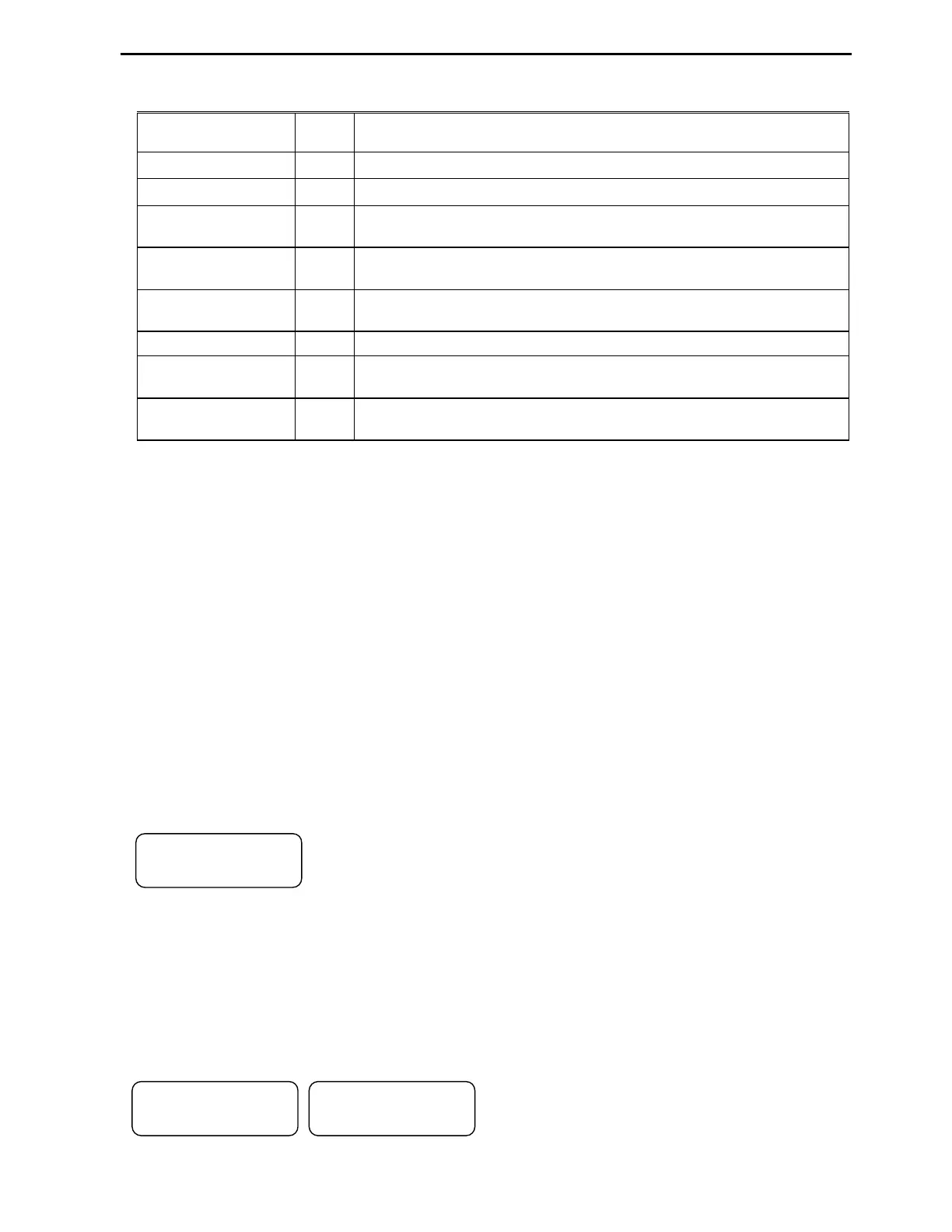
4.1.4 Parameter groups
All P Series VFD parameters are divided in eight program groups by functionality.
Parameter Group Code
Description
Set Group SET Application selection, Motor Data, Basic control and timers settings, PID.
Drive Group DRV Step Frequencies and monitoring parameters
Function Group1 FG1
Max. Frequency, Control Modes selections, Pre-heat, Motor Overload
Protection, VFD overload protection, and Run Delay.
Function Group2 FG2
Fault History, Dwell Time, Jump Frequencies, Motor Slip, Auto Tune,
Torque Boost, Parameter Save and Lock, Auto Reset, Power-up delay.
Input / Output Group I/O
Programmable Digital and Analog Inputs and Outputs Settings,
Damper/Lube Selection. RS485 communication settings.
Application Group APP External PID settings.
Extension Group EXT
Shows the model of installed SUB board and settings for it.
Available when SUB board is installed.
Communication
Group
COM
Shows the model of communication Board and all the settings for it.
Available when COM board is installed.
Note: Refer to the parameter function descriptions for detailed information for each group.
Some groups are available only when Option Board is installed. When a new VFD is powered up, the
proper application type must be selected in initial parameter SET-00 in order to have access to other
parameters.
The programming of VFD parameters can be done by utilizing a 32-character alphanumeric LCD keypad
or DriveView PC software. Se the list of parameter groups in the table below.
4.2 Control Modes
4.2.1 Easy Start Mode
Easy Start mode allows controlling VFD start/stop from keypad. This mode is activated by pressing
[STOP] key on the Keypad for more than 3 seconds when VFD is at stop mode and VFD is ready for
operation via Keypad (FWD/REV RUN and STOP). The Drive mode is set to V/F and frequency
reference to JOG. Press [SHIFT] key when VFD is in stop mode in order to switch to regular control
mode.
4.2.2 Keypad Control Mode
In order to control Start/Stop Forward or Reverse command and speed reference of the VFD from a
Keypad, set Drive Mode parameter SET-09 to Keypad and Speed Ctrl parameter SET-10 to a Keypad-1.
The display should show the following screen. Now VFD is ready to be controlled by the keypad.
If frequency command needs to be changed, press [ENTER] key, then
[SHIFT] key to move flashing cursor to proper position and [
]
or [
]
key to
change the number, then press [ENTER] key to finish programming. Press
[FWD] or [REV] key to start VFD in forward or reverse direction and [STOP] key to stop it. If VFD
loses power during run mode and then receives power again, it stays in Stop mode until [FWD] or [REV]
key is pressed.
4.2.3 Remote (Terminal) Control Mode
In order to control VFD Start/Stop Forward or Reverse command and speed reference of the VFD from
external controller via VFD terminals, set Drive Mode parameter SET-09 to Remote-1 and Speed Ctrl
parameter SET-10 to V1 for 0-10VDC and I for 4-20mA signals. The display should show one of the
following screens.
Wire the control and speed signal wires to VFD and
it is ready to be controlled by external controller.
When VFD is at stop mode, the parameter DRV-00
shows frequency reference Hz coming from external analog signal source. When VFD started, this display
shows VFD actual output frequency.
"'▶44
55 *1 555578
"'▶'
55 *1 555578
"'▶< 556
55 *1 555578