Chapter 8 - Troubleshooting & Maintenance
8-5
8.5 Maintenance
The P series VFD is an industrial electronic product with advanced semiconductor components and its
operation depends on installation and operation conditions such as temperature, humidity, vibration, dust etc.
It is recommended to perform routine inspections of all operating VFDs.
8.5.1 Precautions
☞ Remove the VFD input power while performing maintenance procedures.
☞ Use a true RMS multimeter to check VFD output voltage. Other type of voltmeters cannot read VFD high
frequency PWM output voltage correctly.
8.5.2 Periodic Inspection
☞ Check for loose connections, bolts, nuts or rust build up caused by surrounding conditions.
☞ Remove any built up dirt or debris in the VFD-cooling fans using compressed air. Replace cooling fans if
debris cannot be completely removed or if cooling fans no longer spin freely for any reason
☞ Carefully remove an built up dirt or debris inside the VFD and on the surface of all circuit boards using
compressed air. If debris build up cannot be removed easily, call Cerus for support.
☞ Check for any discoloration or visual damage to the various connectors inside the VFD. Call Cerus for
support if any discolored or damaged connectors are found.
☞ Check the visual condition of the DC Bus capacitors. If any capacitors are bulging, deformed, or have
ruptured in any way, call Cerus for troubleshooting advice and possible solutions.
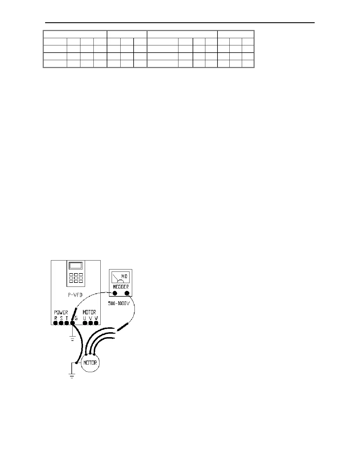
8.5.3 Motor Winding Megger Test
The Megger tester provides 500-1000V output to test motor ground
leak path resistance (windings insulation). Only perform a Megger
test of the motor windings after the motor wiring is disconnected
from VFD.
Good windings should have insulation resistance in the Mega Ohm
range.
Do not connect Megger tester leads to VFD power terminals,
otherwise VFD power components can be damaged.
Do not perform Megger test on control wiring.
to
R S T R S T
to
R S T R S T
State
O C C C C C
State
C C C O O O
U V W U V W
U V W U V W
State
O O O C C C
State
C C C O O O